The building, or any structure in the plan, is divided by conditional axial lines into a number of segments. These lines that determine the position of the main load-bearing structures are called longitudinal and transverse coordination axes.
The interval between the coordination axes in the plan of the building is called a step, and in the predominant direction the step can be longitudinal or transverse.
In the event that the distance between the coordinating longitudinal axes coincides with the span, overlap or coating of the main supporting structure, then this interval is called the span.
For floor height H This is the distance from the floor level of the selected floor to the floor level of the floor above. By the same principle, the height of the upper floor is also determined, at which the thickness of the attic floor is assumed to be conditionally equal to the thickness of the interfloor floor c. In industrial one-story buildings, the floor height is equal to the distance from the floor to the bottom surface of the roof structure.
In order to determine the relative position of the parts of the building, a grid of coordination axes is used that determines the supporting structures of this building.
Drawing coordination axes.
Coordination axes are stroked with dotted thin lines and marked inside circles with a diameter of 6 to 12 mm. The diameter of the circles must correspond to the scale of the drawing: 6 mm - for 1:400 or less; 8 mm - for 1:200 - 1:100; 10 mm - for 1:50; 12 mm for 1:25; 1:20; 1:10. The direction of the marking of the axes is applied from left to right, horizontally and from bottom to top, vertically.
If the coordination axes of the opposite sides of the plan do not coincide, the designations of the indicated axes at the divergence points are additionally applied on the upper and / or right sides. For individual elements located between the coordination axes of the main supporting structures, additional axes are applied and denoted as a fraction:
- above the line indicate the designation of the previous coordination axis;
- under the line - an additional serial number within the area between adjacent coordination axes in accordance with the figure.
It is allowed to assign numerical and alphabetic designations to the coordinating axes of half-timbered columns in continuation of the designations of the axes of the main columns without an additional number.

Binding of coordination axes occurs according to the rules described in paragraph 4 GOST 28984-91. Example:
The binding of load-bearing walls made of piece materials to the coordination axes should be carried out in compliance with the following rules:
- a) when resting directly on the walls of the coating slabs, the inner surface of the wall should be taken from the longitudinal coordination axis at a distance of 130 mm for brick walls and 150 mm for block walls;
- b) when supporting the walls of the supporting structures of the coating (beams) with a brick wall thickness of 380 mm or more (for blocks of 400 m or more), the longitudinal coordination axis should pass at a distance of 250 mm from the inner surface of the wall (300 mm for a wall of blocks);
- c) at brick walls ax 380 mm thick with pilasters 130 mm wide, the distance from the longitudinal axis to the inner surface of the wall should be 130 mm;
- d) with brick walls of any thickness with pilasters with a thickness of more than 130 mm, the inner surface of the walls is combined with coordination axis("zero" binding);
- e) the binding of the bearing end wall when the roof slabs are supported on it should be taken the same as when the roof slabs are supported on the longitudinal wall;
- e) the geometric axes of the internal load-bearing walls must be aligned with the coordination axes.
When supporting floor slabs for the entire thickness of the bearing wall, it is allowed to align the outer coordination plane of the walls with the coordination axis (Fig. 9d).

Marking of coordination axes.
Coordination axes are marked with Arabic numerals and capital letters, except for the symbols: 3, Y, O, X, S, b, b. The numbers indicate the axes along the side of the building with the largest number of coordination axes. Axes marking is located, as a rule, on the left and lower sides of the building plan. The height of the font denoting the coordination axes is chosen one or two numbers more than the size of the numbers on the same sheet. Omissions in the numerical and alphabetic designations of the coordination axes are not allowed.
On the image of a repeating element attached to several coordination axes, the coordination axes are designated in accordance with the figure:
- "a" - with the number of coordination axes not more than 3;
- "b" - "" "" more than 3;
- "c" - for all alphabetic and digital coordination axes.
If necessary, the orientation of the coordination axis to which the element is attached, with respect to the neighboring axis, is indicated in accordance with the figure.
The construction of the main elements of buildings is carried out using modular size coordination in construction (MKRS), according to which the dimensions of the main space-planning elements of the building must be a multiple of the module.
The main module is taken equal to 100 mm.
The main structural elements (bearing walls, columns) of the building are located along the modular coordination axes(longitudinal and transverse). The distance between the coordination axes in low-rise buildings are taken as multiples of the 3M module (300 mm).
To determine the relative position of building elements, grid of coordination axes.
Coordination axes are drawn with dash-dotted thin lines and are usually indicated on the left and bottom sides of the plan, marked, starting from the lower left corner, with Arabic numerals (from left to right) and capital letters of the Russian alphabet (from bottom to top) in circles with a diameter of 6 ... 12 mm (Fig. .2).
Rice. 2. An example of marking the coordination axes

Dimensions on construction drawings they are affixed in millimeters and are applied, as a rule, in the form of a closed chain.
Dimension lines are limited to serifs - short strokes 2 ... 4 mm long, drawn with an inclination to the right at an angle of 45 ° to the dimension line. Dimension lines should protrude beyond the extreme extension lines by 1 ... 3 mm. The dimension number is located above the dimension line at a distance of 1 ... 2 mm (Fig. 3, a).
To designate cutting plane positions section or section of a building, an open line is used in the form of separate thickened strokes with arrows indicating the direction of view. The cut line is marked with Arabic numerals (Fig. 3, c). The start and end strokes must not cross the outline of the image.
The dimensions of buildings in height (height of floors) are assigned as multiples of the modules. Floor height of a building is defined as the distance from the floor level of a given floor to the floor level of an overlying floor. In projects of residential buildings, the floor height is assumed to be 2.8; 3.0; 3.3 m
On facades and sections, high-rise marks the level of an element or structure of a building from any calculated level taken as zero. Most often, the level of the finished floor (floor covering) of the first floor is taken as the zero level (mark ± 0.000).
Level marks are indicated in meters with three decimal places without indicating units of length and are placed on extension lines in the form of an arrow with a shelf. The sides of the right angle of the arrow are drawn by a solid thick main line at an angle of 45 ° to the extension line (Fig. 4).

Rice. 3. Inscription of the dimensions and position of the cuts:
a - dimensions and dimension lines; b – gaze direction arrow;
c - positions of cuts
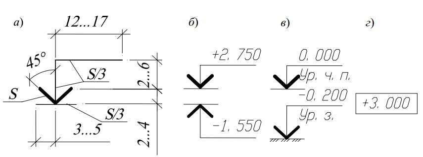
Rice. 4. Drawing level marks on the views:
a - dimensions of the level mark; b - examples of location and design
level marks on cuts and sections; c – the same, with explanatory inscriptions;
d - an example of the image of the level sign on the plans
The mark mark may be accompanied by explanatory inscriptions: Ur.ch.p. - the level of the clean floor; Ur.z. - ground level.
Marks on the plans are applied in rectangles (Fig. 4, d). Marks above zero level are indicated with a plus sign (for example, + 2.700), below zero - with a minus sign (for example, - 0.200).
The following are accepted in construction drawings: denominations types of buildings.
V names of plans the building indicates the mark of the finished floor of the floor, the floor number or the designation of the corresponding plane; when executing a part of the plan - the axes that limit this part, for example:
Elevation plan +3,000;
2nd floor plan;
Plan 3–3;
Elevation plan 0.000 in axes 21–39, A–D.
V name of cuts of the building, the designation of the corresponding secant plane is indicated (in Arabic numerals), for example, Section 1–1.
V names of facades of the building, the extreme axes are indicated, between which the facade is located, for example:
Facade 1–5;
Facade 12–1;
Facade A-G.
For multilayer structures, portable inscriptions located on shelves in a straight line,
ending with an arrow (Fig. 5). The sequence of inscriptions (material or construction of layers with indication of their thickness) to individual layers must correspond to the sequence of their location on the drawing from top to bottom and from left to right.
On the leader lines, ending with a shelf, additional explanations to the drawing or item numbers of elements in the specification are placed.

Rice. 5. Examples of execution of portable inscriptions
Graphic symbols materials in sections and sections of buildings and structures are given in App. 3. The distance between parallel hatching lines is selected within 1 ... 10 mm, depending on the hatching area and image scale. Material designations are not used in the drawings if the material is homogeneous, if the dimensions of the image do not allow the symbol to be applied.
Conditional graphic images of building elements and sanitary devices are given in App. 4.
Introduction date 01.01.71
This standard establishes the rules for the representation of objects (products, structures and their constituent elements) in the drawings of all industries and construction. The standard fully complies with ST SEV 363-88. (Revised edition, Rev. No. 2).
1. BASIC PROVISIONS AND DEFINITIONS
1.1. Images of objects should be made using the rectangular projection method. In this case, the object is assumed to be located between the observer and the corresponding projection plane (Fig. 1).1.2. Six faces of a cube are taken as the main projection planes; the edges are aligned with the plane, as shown in Fig. 2. Face 6 may be placed next to face 4. 1.3 The image on the front projection plane is taken as the main one in the drawing. The object is positioned relative to the frontal plane of projections so that the image on it gives the most complete idea of the shape and size of the object. 1.4. Images in the drawing, depending on their content, are divided into views, sections, sections.

Crap. 2 Damn. 3
1.5. View - the image of the visible part of the surface of the object facing the observer. To reduce the number of images, it is allowed to show in the views the necessary invisible parts of the surface of the object using dashed lines (Fig. 3).

1.6 Section - an image of an object mentally dissected by one or more planes, while the mental dissection of the object refers only to this section and does not entail changes in other images of the same object. The section shows what is obtained in the cutting plane and what is located behind it (Fig. 4). It is allowed to depict not everything that is located behind the cutting plane, if this is not required to understand the design of the object (Fig. 5).

1.7. Section - an image of a figure obtained by mentally dissecting an object with one or more planes (Fig. 6). The section shows only what is obtained directly in the cutting plane. It is allowed to use a cylindrical surface as a secant, which is then developed into a plane (Fig. 7).


(Revised edition, Rev. No. 2). 1.8. The number of images (views, sections, sections) should be the smallest, but providing a complete picture of the subject when using the symbols, signs and inscriptions established in the relevant standards.
2. TYPES
2.1. The following names of views obtained on the main projection planes are established (main views, Fig. 2): 1 - front view (main view); 2 - top view; 3 - left side view; 4 - right side view; 5 - bottom view; 6 - rear view. In construction drawings, if necessary, other names can be assigned to the corresponding views, for example, "facade". The names of the views in the drawings should not be inscribed, with the exception of the case provided for in clause 2.2. In construction drawings, it is allowed to inscribe the name of the view with the assignment of an alphabetic, numeric or other designation to it. 2.2. If the top, left, right, bottom, rear views are not in direct projection connection with the main image (view or section shown on the frontal projection plane), then the projection direction should be indicated by an arrow next to the corresponding image. The same capital letter should be applied above the arrow and above the resulting image (view) (Fig. 8).
Drawings are drawn up in the same way if the listed views are separated from the main image by other images or are not located on the same sheet with it. When there is no image on which the direction of view can be shown, the name of the species is inscribed. In construction drawings, it is allowed to indicate the direction of view with two arrows (similar to indicating the position of cutting planes in sections). In construction drawings, regardless of the relative position of the views, it is allowed to inscribe the name and designation of the view without indicating the direction of view with an arrow, if the direction of view is determined by the name or designation of the view. 2.3. If any part of the object cannot be shown on the views listed in clause 2.1 without distorting the shape and size, then additional views are used that are obtained on planes that are not parallel to the main projection planes (Fig. 9-11). 2.4. The additional view should be marked on the drawing with a capital letter (Fig. 9, 10), and the object associated with the additional view of the image should have an arrow indicating the direction of view, with the corresponding letter designation (arrow B, Fig. 9, 10).


When an additional view is located in direct projection connection with the corresponding image, the arrow and view designation are not applied (Fig. 11).

2.2-2.4. (Revised edition, Rev. No. 2). 2.5. Additional views are arranged as shown in Fig. 9- 11. Location of additional views according to hell. 9 and 11 are preferred. An additional view is allowed to be rotated, but with the preservation, as a rule, of the position adopted for this object on the main image, while the view designation must be supplemented with a conventional graphic designation. If necessary, indicate the angle of rotation (Fig. 12). Several identical additional views related to one subject are designated by one letter and one view is drawn. If at the same time the parts of the object associated with the additional view are located at different angles, then a conditional graphic symbol is not added to the view designation. (Changed edition, Rev. No. 1, 2). 2.6. The image of a separate, limited place on the surface of an object is called a local view (view D, Fig. 8; view D, Fig. 13). The detail view may be limited to a cliff line, if possible in smallest size(view D, drawing 13), or not limited (view D, drawing 13). The local view should be marked on the drawing like additional view. 2.7. The ratio of the sizes of the arrows indicating the direction of view should correspond to those shown in Fig. 14.2.6, 2.7. (Revised edition, Rev. No. 2).


3. SECTIONS
3.1. The sections are divided, depending on the position of the cutting plane relative to the horizontal projection plane, into: horizontal - the cutting plane is parallel to the horizontal projection plane (for example, section A-A, Fig. 13; cut B-B, crap. 15). In construction drawings, horizontal sections may be given other names, for example, "plan"; vertical - the cutting plane is perpendicular to the horizontal plane of the projections (for example, a section at the site of the main view, Fig. 13; sections A-A, B-B, G-D, Fig. 15); inclined - the cutting plane makes an angle with the horizontal projection plane that is different from the right one (for example, section B-B, crap. eight). Depending on the number of cutting planes, the cuts are divided into: simple - with one cutting plane (for example, Fig. 4, 5); complex - with several cutting planes (for example, section A-A, Fig. 8; section B-B, Fig. 15). 3.2. A vertical section is called frontal if the cutting plane is parallel to the frontal plane of projections (for example, section, Fig. 5; section A-A, Fig. 16), and profile if the cutting plane is parallel to the profile plane of projections (for example, section B-B, Fig. . thirteen).


3.3. Complex cuts are stepped if the cutting planes are parallel (for example, a stepped horizontal cut B-B, Fig. 15; a stepped frontal cut A-A, Fig. 16), and broken if the cutting planes intersect (for example, cuts A-A, lines 8 and 15). 3.4. The cuts are called longitudinal if the cutting planes are directed along the length or height of the object (Fig. 17), and transverse if the cutting planes are directed perpendicular to the length or height of the object (for example, sections A-A and B-B, Fig. 18). 3.5. The position of the cutting plane is indicated on the drawing by a section line. An open line must be used for the section line. With a complex cut, strokes are also carried out at the intersections of the secant planes with each other. On the initial and final strokes, arrows should be placed indicating the direction of the gaze (Fig. 8-10, 13, 15); arrows should be applied at a distance of 2-3 mm from the end of the stroke. The start and end strokes must not cross the outline of the respective image. In cases like the one indicated in hell. 18, arrows indicating the direction of view are drawn on the same line. 3.1-3.5. (Revised edition, Rev. No. 2). 3.6. At the beginning and end of the section line, and, if necessary, at the intersection of the secant planes, they put the same capital letter of the Russian alphabet. The letters are applied near the arrows indicating the direction of view, and at the intersections from the outside corner. The cut must be marked with an inscription of the type "A-A" (always two letters separated by a dash). In construction drawings, instead of letters, it is allowed to use numbers instead of letters at the section line, as well as to inscribe the name of the section (plan) with the alphanumeric or other designation assigned to it. 3.7. When the cutting plane coincides with the plane of symmetry of the object as a whole, and the corresponding images are located on the same sheet in direct projection connection and are not separated by any other images, the position of the cutting plane is not marked for horizontal, frontal and profile cuts, and the cut is labeled do not accompany (for example, a section in place of the main view, Fig. 13). 3.8. The frontal and profile sections, as a rule, are given a position corresponding to that adopted for a given object in the main image of the drawing (Fig. 12). 3.9. Horizontal, frontal and profile sections can be located in the place of the corresponding main views (Fig. 13). 3.10. A vertical section, when the cutting plane is not parallel to the frontal or profile projection planes, as well as an oblique section, should be built and located in accordance with the direction indicated by the arrows on the section line. It is allowed to place such sections anywhere in the drawing (section B-B, Fig. 8), as well as with a rotation to the position corresponding to that adopted for this object on the main image. In the latter case, a conventional graphic designation must be added to the inscription (section Г-Г, Fig. 15). 3.11. With broken cuts, the secant planes are conditionally rotated until aligned in one plane, while the direction of rotation may not coincide with the direction of view (Fig. 19). If the combined planes turn out to be parallel to one of the main projection planes, then a broken section can be placed in place of the corresponding type (sections A-A, Fig. 8, 15). When the cutting plane is rotated, the elements of the object located on it are drawn as they are projected onto the corresponding plane with which they are aligned (Fig. 20).

Crap. 19 Damn. twenty
3.12. A section that serves to clarify the structure of an object only in a separate, limited place is called local. The local section is highlighted in the view by a solid wavy line (Fig. 21) or a solid thin line with a break (Fig. 22). These lines must not overlap with any other lines in the image.


3.13. Part of the view and part of the corresponding section may be connected, separating them with a solid wavy line or a solid thin line with a break (Fig. 23, 24, 25). If at the same time half of the view and half of the section are connected, each of which is a symmetrical figure, then the dividing line is the axis of symmetry (Fig. 26). It is also allowed to separate the section and the view with a dash-dotted thin line (Fig. 27), coinciding with the trace of the plane of symmetry not of the entire object, but only of its part, if it represents a body of revolution.


3.10-3.13. (Revised edition, Rev. № 2). 3.14. It is allowed to connect a quarter of a view and a quarter of three sections: a quarter of a view, a quarter of one section and a half of another, etc., provided that each of these images individually is symmetrical.
4. SECTIONS
4.1. Sections that are not part of the section are divided into: remote (Fig. 6, 28); superimposed (Fig. 29).

Remote sections are preferred and they can be placed in a section between parts of the same type (Fig. 30).

(Revised edition, Rev. No. 2). 4.2. The contour of the removed section, as well as the section that is part of the section, is depicted by solid main lines, and the contour of the superimposed section is depicted by solid thin lines, and the image contour at the location of the superimposed section is not interrupted (Fig. 13, 28, 29). 4.3. The axis of symmetry of the extended or superimposed section (Fig. 6, 29) is indicated by a dash-dotted thin line without letters and arrows, and the section line is not drawn. In cases like the one indicated in hell. 30, with a symmetrical section figure, the section line is not drawn. In all other cases, an open line is used for the section line with arrows indicating the direction of view and denote it with the same capital letters of the Russian alphabet (in construction drawings - in capital or lowercase letters of the Russian alphabet or numbers). The section is accompanied by an inscription of the type "A-A" (Fig. 28). In construction drawings, it is allowed to inscribe the name of the section. For asymmetric sections located in a gap (Fig. 31) or superimposed (Fig. 32), the section line is drawn with arrows, but is not marked with letters.

Crap. 31 Damn. 32
In construction drawings, with symmetrical sections, an open line is used with its designation, but without arrows indicating the direction of view. 4.4. The section by construction and location must correspond to the direction indicated by the arrows (Fig. 28). It is allowed to place the section at any place of the drawing field, as well as with a rotation with the addition of a conventional graphic symbol 4.5. For several identical sections related to one object, the section line is indicated by one letter and one section is drawn (Fig. 33, 34). If at the same time the cutting planes are directed at different angles (Fig. 35), then the conventional graphic designation is not applied. When the location of identical sections is precisely determined by the image or dimensions, it is allowed to draw one section line, and indicate the number of sections above the section image.

Crap. 33 Damn. 34

Crap. 35 Damn. 36
4.6 Cutting planes are chosen so as to obtain normal cross sections (Fig. 36). 4.7. If the cutting plane passes through the axis of the surface of revolution that bounds the hole or recess, then the contour of the hole or recess in the section is shown in full (Fig. 37). 4.8. If the section is obtained consisting of separate independent parts, then cuts should be used (Fig. 38).

Crap. 37 Damn. 38
4.4-4.8. (Revised edition, Rev. No. 2).
5. REMOTE ELEMENTS
5.1. Remote element - an additional separate image (usually enlarged) of any part of an object that requires graphic and other explanations regarding the shape, size and other data. The view may contain details not shown in the corresponding image, and may differ from it in content (for example, the image may be a view, and the view may be a section). 5.2. When using a remote element, the corresponding place is marked on the view, section or section with a closed solid thin line - a circle, an oval, etc. with the designation of the external element in a capital letter or a combination of a capital letter with an Arabic numeral on the leader line shelf. Above the image of the remote element indicate the designation and scale in which it is made (Fig. 39).
In construction drawings, a remote element in the image can also be marked with a curly or square bracket or not marked graphically. The image, from where the element is taken out, and the external element, it is also allowed to apply the letter or numeric (in Arabic numerals) designation and name assigned to the external element. (Revised edition, Rev. No. 2). 5.3. The remote element is placed as close as possible to the corresponding place on the object image.
6. CONDITIONS AND SIMPLIFICATIONS
6.1. If the view, section or section represents a symmetrical figure, it is allowed to draw half of the image (view B, Fig. 13) or a little more than half of the image with a break line drawn in the latter case (Fig. 25). 6.2. If an object has several identical, evenly spaced elements, then one or two such elements are fully shown on the image of this object (for example, one or two holes, Fig. 15), and the remaining elements are shown in a simplified or conditional way (Fig. 40). It is allowed to depict a part of an object (Fig. 41, 42) with proper indications of the number of elements, their location, etc.
Crap. 40 Damn. 41 Damn. 42
6.3. On views and sections, it is allowed to depict projections of lines of intersection of surfaces in a simplified way, if their exact construction is not required. For example, instead of curved curves, arcs of a circle and straight lines are drawn (Fig. 43, 44).


6.4. A smooth transition from one surface to another is shown conditionally (Fig. 45-47) or not shown at all (Fig. 48-50).


![]()

Simplifications similar to those shown in Fig. are allowed. 51, 52.


6.5. Details such as screws, rivets, keys, non-hollow shafts and spindles, connecting rods, handles, etc., are shown undissected when viewed longitudinally. Balls are always shown uncut. As a rule, nuts and washers are shown uncut on assembly drawings. Elements such as the spokes of flywheels, pulleys, gears, thin walls such as stiffeners, etc. are shown unshaded if the cutting plane is directed along the axis or long side of such an element. If in such elements of the part there is a local drilling, recess, etc., then a local cut is made, as shown in Fig. 21, 22, 53. (Changed edition, Rev. No. 2).

Crap. 53 Damn. 54 Damn. 55
6.6. Plates, as well as elements of parts (holes, chamfers, grooves, recesses, etc.) with a size (or difference in size) in the drawing of 2 mm or less, are depicted with a deviation from the scale adopted for the entire image, towards the increase. 6.7. A slight taper or slope is allowed to be depicted with magnification. On those images in which the slope or taper is not clearly identified, for example, the main view of the devil. 54a or a top view of hell. 54b, only one line is drawn, corresponding to the smaller size of the element with a slope or the smaller base of the cone. 6.8. If it is necessary to highlight the flat surfaces of the object in the drawing, diagonals are drawn on them with solid thin lines (Fig. 55). 6.9. Objects or elements that have a constant or regularly changing cross section (shafts, chains, bars, shaped steel, connecting rods, etc.) are allowed to be depicted with breaks. Partial images and images with breaks are limited in one of the following ways: a) by a continuous thin line with a break, which can extend beyond the image contour by a length of 2 to 4 mm. This line may be inclined relative to the contour line (Fig. 56a);

B) a solid wavy line connecting the corresponding contour lines (Fig. 56b);

C) hatching lines (Fig. 5bc).
(Revised edition, Rev. № 2). 6.10. On the drawings of objects with a continuous mesh, braid, ornament, relief, knurling, etc., it is allowed to depict these elements in part, with possible simplification (Fig. 57).

6.11. To simplify the drawings or reduce the number of images, it is allowed: a) to depict the part of the object located between the observer and the cutting plane with a dash-dot thickened line directly on the section (superimposed projection, Fig. 58); b) apply complex cuts (Fig. 59);


C) to show holes in the hubs of gears, pulleys, etc., as well as for keyways, instead of a complete image of the part, give only the outline of the hole (Fig. 60) or groove (Fig. 52); d) depict in section the holes located on the round flange when they do not fall into the cutting plane (Fig. 15). 6.12. If the top view is not necessary and the drawing is made up of images on the frontal and profile projection planes, then with a stepped cut, the section line and inscriptions related to the section are applied as shown in Fig. 61.


6.11, 6.12. (Revised edition, Rev. No. 2). 6.13. The conventions and simplifications allowed in permanent connections, in the drawings of electrical and radio engineering devices, gears, etc., are established by the relevant standards. 6.14. The conditional graphic designation "rotated" must correspond to the devil. 62 and "deployed" - hell. 63.


(Introduced additionally, Amendment No. 2). APPENDIX according to GOST 2.317-69.
INFORMATION DATA
1. DEVELOPED AND INTRODUCED by the Committee of Standards, Measures and Measuring Instruments under the Council of Ministers of the USSR DEVELOPERS V.R. Verchenko, Yu.I. Stepanov, Ya.G. Old-timer, B.Ya. Kabakov, V.K. Anopova 2. APPROVED AND INTRODUCED BY the Decree of the Committee of Standards, Measures and Measuring Instruments under the Council of Ministers of the USSR in December 1967. 3. The standard fully complies with ST SEV 363-88 4. INSTEAD OF GOST 3453-59 regarding sect. I - V, VII and appendices 5. EDITION (April 2000) with Amendments No. 1, 2, approved in September 1987, August 1989 (IUS 12-87, 12-89)
| 1. Basic provisions and definitions. 1 2. Views.. 3 3. Sections.. 6 4. Sections. 9 5. External elements. 11 6. Conventions and simplifications. 12 |
Structural size call the design size l building structure, product, element, element of equipment, determined in accordance with the rules of the MKRS (modular coordination of dimensions in construction). Structural dimensions (Fig. 109) take less coordination dimensions l 0 by a gap size of d or more coordination dimensions (with the addition of the value of the protrusions located in the adjacent coordination space). The size of the gap d is set in accordance with the features of the structural units, the operating conditions of the joints, installation and tolerances.
Nominal dimensions l 0 structural elements are the design dimensions. building products and equipment, including standardized clearances d; the normalized gap is the thickness of the seam of the gap between the structural elements established by the norms.
Structural dimensions l- design dimensions of structural elements, building products and equipment.
Rice. 109. Location building structures, products and elements in the coordination space
Natural dimensions structural elements - these are their actual dimensions, which differ from the structural ones by the amount of tolerances established by the standards.
Features of dimensioning on construction drawings. on construction drawings, dimensions are applied in accordance with GOST 2.307-68, taking into account the requirements of the system project documentation for construction GOST 21.501-93.
To determine the dimensions of the depicted product (structural element, assembly, building, structure) and its parts, the dimensional numbers printed on the drawing are used. Dimension and extension lines are drawn as a solid thin line with a thickness of S/3 to S/2 (see Fig. 109).
Dimensions in millimeters on construction drawings, as a rule, are applied in the form of a closed chain without indicating the unit of measurement. If the dimensions are given in other units, this is specified in the notes to the drawings. Dimension lines on construction drawings are limited by serifs - short strokes 2-4 mm long, drawn with an inclination to the right at an angle of 45 ° to the dimension line. The thickness of the serif line is equal to the thickness of the solid main line adopted in this drawing. Dimension lines should protrude beyond the extreme extension lines by 1-3 mm. The dimension number is placed above the dimension line at a distance of approximately 0.5 to 1 mm (Fig. 110a, 110b). The extension line should protrude beyond the dimension line by 1-5 mm. With a lack of space for serifs on dimension lines, which are a closed chain, serifs can be replaced with dots (Fig. 110c).

Rice. 110. Limiting dimension lines
The distance from the drawing outline to the first dimension line is recommended to be at least 10 mm. However, in the practice of design work, this distance is taken equal to 14-21 mm. The distance between parallel dimension lines must be at least 7 mm, and from the dimension line to the circle of the coordination axis - 4 mm (Fig. 111).

Rice. 111. An example of applying dimensions to an image with a gap
with one dimension line
If there are a number of identical elements in the image located at equal distances from each other (for example, the axes of columns), the dimensions between them are put down only at the beginning and at the end of the row (Fig. 112) and indicate the total size between the extreme elements as the product of the number of repetitions by repeating size.
The dimension line on construction drawings is limited by arrows in accordance with GOST 2.307-68 if it is required to indicate the diameter, radius of the circle or angle, as well as when applying dimensions from a common base located on a common dimension line (Fig. 113b and Fig. 114)
Rice. 112. An example of applying dimensions to an image with a gap
with multiple dimension lines


Rice. 114. Dimension line
6.6. Building plan
Plan- this is an image of a section of a building, dissected by an imaginary horizontal plane passing at a certain level, as shown in Fig. 115.
According to GOST 21.501–93, this plane should be located at 1/3 of the height of the depicted floor. For residential and public buildings, the imaginary cutting plane is located within the door and window openings of the floor.

A building plan drawing shows what is in the cutting plane and what is below it. Thus, the plan of the building is its horizontal section.
The building plan gives an idea of the shape of the building in plan and the relative position of the individual rooms. The building plan shows window and door openings, the location of partitions and main walls, built-in wardrobes, sanitary Technical equipment etc. Plumbing fixtures are drawn on the building plan on the same scale as the building plan.
If the plan, facade and section of the building are placed on one sheet, then the plan is placed under the facade in projection connection with it. However, due to large sizes images, plans are usually placed on separate sheets, while their long side is located along the sheet.
When starting to draw a plan, it should be remembered that the side of the plan corresponding to the main facade of the building should be turned to the bottom edge of the sheet. When determining a place on a sheet for a drawing of a building plan, the applied dimensions and marking of the coordination axes should be taken into account. Therefore, the plan drawing should be located approximately at a distance of 75 - 80 mm from the sheet frame. In specific cases, these dimensions may vary. After determining the location of the plan on the sheet and its scale, they begin to draw.
1. Draw with a dash-dotted line 0.3 ... 0.4 mm thick the coordination axes of the plan, longitudinal and transverse, as shown in fig. 116. These axes are used to link the building to the construction coordinate grid, as well as to determine the position of load-bearing structures, since these axes are carried out only along the main walls and columns.
The Arabic numerals 1, 2, 3, etc. are used to mark the axes on the side of a building with a large number of them. Most often, a greater number of axes run across the building. To mark the axes on the side of the building with a smaller number, they use the letters of the Russian alphabet A, B, C, etc. Letters mark, as a rule, the axis running along the building. When marking axes, it is not recommended to use the letters: Z, Y, O, X, C, H, SH, Y, b, b. Axes are marked from left to right and from bottom to top. Omissions in the serial numbering and alphabet when designating the coordination axes are not allowed. Usually marking circles (their diameter is 6 ... .12 mm) are located on the left and lower side of the building. Removing the marking circle from the last dimension line 4 mm (see fig. 112)

2. Taking into account the binding of the axes along the MKRS and the thickness of the walls, the contours of the longitudinal and transverse outer and inner walls are drawn with thin lines (Fig. 117).

The main walls are tied to the coordination axes, i.e. determine the distances from the inner and outer plane of the wall to the coordination axis of the building, and the axis can not be drawn along the entire length of the wall, but only by the amount necessary to set the dimensions of the binding. Coordination axes do not always have to coincide with the geometric axes of the walls. Their position should be set taking into account the coordination dimensions used by the standard span structures of beams, trusses or floor slabs. In buildings with load-bearing longitudinal and transverse walls, the binding is performed in accordance with the following guidelines.
In outdoor load-bearing walls the coordination axis passes from the inner plane of the walls at a distance equal to half the nominal thickness of the inner load-bearing wall, a multiple of the module or its half. In brick walls, this distance is most often taken equal to 200 mm, or equal to the module, i.e. 100 mm (Fig. 118a). In external self-supporting walls, if the floor panels do not go into it, for the convenience of calculating the number of standard floor elements, the coordination axis is combined with the inner face of the wall, which is called zero binding (Fig. 118b). If the floor elements rest on the outer wall throughout its entire thickness, the coordination axis is aligned with the outer edge of the wall (Fig. 118c). In internal walls the geometric axis of symmetry coincides with the coordination axis (Fig. 118d). Deviation from this rule is allowed for the walls of staircases and walls with ventilation ducts.

Draw the contours of the partitions with two thin lines (Fig. 117). Partitions are tied to marking axes depending on the layout of the premises in the building.
It is necessary to pay attention to the difference in the connection of external and internal main walls and main walls and partitions. If the material of the connected walls is the same, then the walls are drawn as a single unit. If the material of the walls is different, then they are drawn as different elements.
3. At this stage, flights of stairs are depicted and window and door openings are broken down (Fig. 119).

When drawing flights of stairs, the gap between flights should be selected within 100–200 mm, and the width of the treads should be 300 mm.
The symbol for window and door openings with and without filling is shown in accordance with GOST 21.501–93. When drawing a plan on a scale of 1:50 or 1:100, if there are quarters in the openings, their conditional image is given in the drawing. It should be borne in mind that the dimensions of the openings are indicated in GOST without taking into account quarters, therefore, in the drawings, the dimensions are affixed minus quarters, i.e. subtract 130mm from the size of the opening.
It should be remembered that when drawing a partition that limits the vestibule of the entrance, it must be applied after drawing tape marches. This is due to the fact that the dimensions of the vestibule are limited by the dimensions of the interfloor area. The width of the doorway in this partition is similar to the width of the entrance opening, excluding the quarter (see Fig. 119, 122).
Quarter - this is a protrusion in the upper and side parts of the openings of brick walls, which reduces airflow and facilitates the fastening of boxes (Fig. 120). On fig. 120a shows window openings with and without a quarter, and Figure 120b shows doorways with and without a quarter.
It should be noted that when depicting windows on plans and sections on a scale of M1:100 and M1:50, glazing in window openings with a quarter, the first string of glazing is shown in a quarter, and the second is 1 mm inside the building from the first.

The width of the doors is selected from the range: 700 mm for bathroom and toilet; 800 mm or 900 mm for rooms and kitchens; 900 mm or 1000 mm - entrance doors to the apartment; 1200 mm or 1500 mm (two-leaf) - entrance doors to the entrance. When placing a doorway in the wall for interior doors, one should proceed from the convenience of using the premises, the intended arrangement of furniture, etc., which should be taken into account when determining the direction of door opening.
Some recommendations for door placement: doors in living rooms and the kitchen should open inward; doors leading to the bathroom and toilet open outwards; doors should clutter up the room as little as possible.
On the plans door leafs depicted as a solid thin line and open at an angle of approximately 30º (the angle is not indicated in the drawing). Entrance doors The building only opens to the outside.
4. After depicting windows and doors, they show the location of plumbing equipment (Fig. 119): in the kitchen - a sink and stove, in the toilet - a toilet, in the bathroom - a bath and a washbasin. Conditional graphic images of sanitary equipment are performed in accordance with GOST 2.786-70 * and GOST 21.205-93, the dimensions of the most common sanitary equipment are given in fig. 121.

5. Outline the contours of partitions and main walls with lines of appropriate thickness, put down the dimensions and areas of the premises, as shown in fig. 122. When choosing the thickness of the stroke lines, it should be taken into account that non-load-bearing structures, in particular the contours of partitions, are outlined with lines of smaller thickness than the load-bearing main walls.
Dimensions outside the building plan. The first dimension line (chain) with alternating dimensions of walls and openings is drawn at a distance of 15 ... .20 mm from the outer contour of the plan.
On the second dimensional chain indicate the distance between adjacent coordination axes.
On the third dimensional chain indicate the distance between the extreme coordination axes.
The distance between parallel dimension lines (chains) must be at least 7 mm, and from the dimension line to the marking circle of the coordination axis - 4 mm. Circles for designating coordination axes are taken with a diameter of 6 ... .12 mm.
The dimensions of the binding of the outer walls to the coordination axes are put down before the first dimensional chain.
Horizontal traces of imaginary cutting planes of the section are also applied on the plans, on which images of the sections of the building are then built. These traces are thick open strokes 1 mm thick with arrows as shown in Fig. 122. If necessary, the imaginary plane of the cut can be depicted with a thickened dash-dotted line. The direction of the arrows, i.e. direction of view, it is recommended to take from the bottom up or from right to left. However, if necessary, you can choose another direction. Depending on the position of the dimensional chains and the workload of the drawing, they can be placed at the outline of the plan or behind the extreme dimensional chain, as shown in Fig. 122. The secant planes of the cuts are indicated by the letters of the Russian alphabet or numbers.

Dimensions placed inside the building plan. The internal dimensions of the premises (rooms), the thickness of the partitions, internal walls, the dimensions of the doorways are put down on the internal dimension lines (chains). Internal dimension lines are drawn at a distance of at least 8 ... 10 mm from the wall or partition.
Indicate the width and length of the staircase, the coordination dimensions of the width of the platforms, the length of the horizontal projection of the marches.
The figure of the size of the area with an accuracy of 0.01 m2 is put on the plan in a free place, closer to the lower right corner of each room, underlining it with a solid main line.
Put down the height of the floor and interfloor platforms, and for the first floor - the entrance platform, in a rectangle with an accuracy of the third significant figure after the decimal point, indicating the sign "+" or "-".
An inscription is made above the plan drawing. For industrial buildings, this will be an indication of the floor level production premises or sites according to the type “Plan for elev. +2,500". The word "mark" is abbreviated. For civil buildings in the inscription, you can write the name of the floor according to the type "Plan of the 1st floor". The inscriptions are not underlined.
The plan indicates the name of the premises. If the size of the image does not allow making an inscription on the drawing, then the rooms are numbered, their name is given in the explication. Marking numbers are placed in circles with a diameter of 6 - 8 mm.
Drawings of floor plans are accompanied by an explication of the premises; lists of interior decoration, etc. The shapes and sizes of explications and statements are shown in fig. 123.

● contours of load-bearing walls that fall into the section 0.6 - 0.7mm;
● contours of partitions 0.3 - 0.4mm;
● contours of elements that did not fall into the cut, the image of stairs, plumbing equipment 0.3mm;
● thickness of extension, dimension, center lines, marking circles and other auxiliary lines 0.2mm.
6.7. Control questions
1. What drawings are called construction?
2. List the types of buildings according to their purpose.
3. What is the brand of the main set of working drawings of architectural solutions.
4. What is called a structural element?
5. List the main structural elements of the building.
6. What is a module? What are the meanings of enlarged modules.
7. How are the coordination axes?
8. Features of drawing dimensions on construction drawings.
8. What is called a floor plan?
9. What scale of construction drawings is used to draw plans for residential buildings?
10. How is the plan marked?
11. What is the sequence of the floor plan?
12. How are the mills attached to the marking axes?
13. What is the conditional image in terms of a window opening with a quarter and without quarters?
14. What is the conditional image in terms of a doorway with a quarter and without quarters?
15. How are the elements of sanitary equipment depicted on the plans?
16. What dimensions are applied on the floor plan?
17. How are the areas of premises indicated on the plans?
18. How and what lines are used when tracing the floor plan.
19. What line thickness is used when building a plan
Lecture 7. SECTION
7.1. Level marks of structural elements.
7.2. General information about sections of buildings.
7.3. Methodology for constructing a vertical section of a building.
7.4. Building overlays.
7.5. Construction of window and door openings.
7.5. Control questions.
7.1. Level marks of structural elements
Marks. Conditional level marks (heights, depths) on plans, sections, facades show the distance in height from the surface level of any building structural element located near the planning surface of the earth. This level is taken as zero.
Marks of height levels, depths of structural elements from the reference level (conditional "zero" mark) are indicated in meters with three decimal places separated from the integer by a comma. On facades, sections and sections, marks are placed on the extension lines of the contour.
The conditional "zero" mark is indicated, indicated without the sign " 0,000 ' or with a sign "±0.000" (it is recommended to designate with the sign "±"); marks above zero - with a "+" sign; below zero - with a "-" sign.
On views (facades), sections and sections, marks are placed on extension lines or contour lines and denoted by a conventional sign. The mark mark is (GOST 21.105 - 79) an arrow with a shelf. In this case, the arrow is made with main lines 2-4 mm long, drawn at an angle of 45 ° to the extension line or contour line. The leader line, vertical or horizontal, is outlined with a solid thin line (Fig. 124a, 124b).

If necessary, the height and length of the shelf can be increased. If several level signs are located one above the other near one image, it is recommended to place the vertical lines of the mark on one vertical straight line, and make the length of the horizontal shelf the same (Fig. 124c).
The mark mark may be accompanied by explanatory inscriptions. For instance: " Lv.p.p." - the level of the clean floor; " Ur.z." - ground level (Fig. 124d).
On construction drawings, level marks in sections (Fig. 125a), facades (Fig. 125b) and plans (Fig. 125c) are indicated in meters with three decimal places separated from the integer by a comma.

The conditional zero mark is indicated as follows: 0.000. A dimensional number showing the level of an element located below the zero mark has a minus sign (for example -1.200), and one located above has a plus sign (for example +2.700).
On the plans, the dimensional number of the marks is applied in a rectangle, the outline of which is circled with a thin solid line, or on the shelf of the leader line. In this case, a plus or minus sign is also placed before the dimension number (Fig. 125c).
7.2. General information about building sections
cut called the image of a building, mentally dissected by a vertical plane, fig. 126. If the plane is perpendicular to the longitudinal axes, then the cut is called cross, and parallel to them longitudinal. Sections in construction drawings serve to identify the volumetric and constructive solution buildings, the relative position of individual structures, premises, etc.
Sections are architectural and constructive.
architectural cuts serve to identify the internal appearance of the premises and the location of the architectural elements of the interior, which do not show the structures of floors, rafters, foundations and other elements, but put down the height of the premises, window and door openings, plinth, etc. The heights of these elements are most often determined by elevations. Architectural sections are made at the initial design stage to work out the facade of the building. For the construction of the building, the architectural section is not used, since it does not show the structural elements of the building, fig. 127.
Structural cuts are carried out at the stage of development of working drawings of the building, which show the structural elements of the building (foundations, rafters, ceilings), and also apply the necessary dimensions and marks, fig. 128.


In working drawings, the direction of view for cuts is taken, as a rule, according to the plan - from bottom to top and from right to left. Sometimes, if necessary, or for educational purposes, the direction of gaze is taken from left to right.
The position of the cutting plane is chosen so that it passes through the most structurally or architecturally important parts of the building: window and door openings, stairwells, balconies, etc. It should be borne in mind that the cut plane along the stairs is always carried out along the marches closest to the observer. In this case, the march of the stairs that has fallen into the cut is outlined with a line of greater thickness (solid main) than the march contour along which the cutting plane does not pass. The contour of this march is outlined with a solid thin line.
The construction of the main elements of buildings is carried out using modular size coordination in construction (MKRS), according to which the dimensions of the main space-planning elements of the building must be a multiple of the module.
The main module is taken equal to 100 mm.
The main structural elements (bearing walls, columns) of the building are located along the modular coordination axes(longitudinal and transverse). The distance between the coordination axes in low-rise buildings is taken as a multiple of the 3M module (300 mm).
To determine the relative position of building elements, grid of coordination axes.
Coordination axes are drawn with dash-dotted thin lines and are usually indicated on the left and bottom sides of the plan, marked, starting from the lower left corner, with Arabic numerals (from left to right) and capital letters of the Russian alphabet (from bottom to top) in circles with a diameter of 6 ... 12 mm (Fig. .2).
Rice. 2. An example of marking the coordination axes
Dimensions on construction drawings they are affixed in millimeters and are applied, as a rule, in the form of a closed chain.
Dimension lines are limited to serifs - short strokes 2 ... 4 mm long, drawn with an inclination to the right at an angle of 45 ° to the dimension line. Dimension lines should protrude beyond the extreme extension lines by 1 ... 3 mm. The dimension number is located above the dimension line at a distance of 1 ... 2 mm (Fig. 3, a).
To designate cutting plane positions section or section of a building, an open line is used in the form of separate thickened strokes with arrows indicating the direction of view. The cut line is marked with Arabic numerals (Fig. 3, c). The start and end strokes must not cross the outline of the image.
The dimensions of buildings in height (height of floors) are assigned as multiples of the modules. Floor height of a building is defined as the distance from the floor level of a given floor to the floor level of an overlying floor. In projects of residential buildings, the floor height is assumed to be 2.8; 3.0; 3.3 m
On facades and sections, high-rise marks the level of an element or structure of a building from any calculated level taken as zero. Most often, the level of the finished floor (floor covering) of the first floor is taken as the zero level (mark ± 0.000).
Level marks are indicated in meters with three decimal places without indicating units of length and are placed on extension lines in the form of an arrow with a shelf. The sides of the right angle of the arrow are drawn by a solid thick main line at an angle of 45 ° to the extension line (Fig. 4).
![]()
Rice. 3. Inscription of the dimensions and position of the cuts:
a - dimensions and dimension lines; b – gaze direction arrow;
c - positions of cuts

Rice. 4. Drawing level marks on the views:
a - dimensions of the level mark; b - examples of location and design
level marks on cuts and sections; c – the same, with explanatory inscriptions;
d - an example of the image of the level sign on the plans
The mark mark may be accompanied by explanatory inscriptions: Ur.ch.p. - the level of the clean floor; Ur.z. - ground level.
Marks on the plans are applied in rectangles (Fig. 4, d). Marks above the zero level are indicated with a plus sign (for example, + 2.700), below zero - with a minus sign (for example, - 0.200).
The following are accepted in construction drawings: denominations types of buildings.
V names of plans the building indicates the mark of the finished floor of the floor, the floor number or the designation of the corresponding plane; when executing a part of the plan - the axes that limit this part, for example:
Elevation plan +3,000;
2nd floor plan;
Plan 3–3;
Elevation plan 0.000 in axes 21–39, A–D.
V name of cuts of the building, the designation of the corresponding secant plane is indicated (in Arabic numerals), for example, Section 1–1.
V names of facades of the building, the extreme axes are indicated, between which the facade is located, for example:
Facade 1–5;
Facade 12–1;
Facade A-G.
For multilayer structures, portable inscriptions located on shelves in a straight line,
ending with an arrow (Fig. 5). The sequence of inscriptions (material or construction of layers with indication of their thickness) to individual layers must correspond to the sequence of their location on the drawing from top to bottom and from left to right.
On the leader lines, ending with a shelf, additional explanations to the drawing or item numbers of elements in the specification are placed.

Rice. 5. Examples of execution of portable inscriptions
Graphic symbols materials in sections and sections of buildings and structures are given in App. 3. The distance between parallel hatching lines is selected within 1 ... 10 mm, depending on the hatching area and image scale. Material designations are not used in the drawings if the material is homogeneous, if the dimensions of the image do not allow the symbol to be applied.
Conditional graphic images of building elements and sanitary devices are given in App. 4.
Annex 3
GRAPHIC DESIGNATION OF MATERIALS IN SECTIONS,
SECTIONS AND VIEWS


Appendix 4
GRAPHIC IMAGES OF BUILDING ELEMENTS

Categories: / /
Tags:
The coordination axes are applied to the images of the building, structures with thin dash-dotted lines with long strokes, denoted by Arabic numerals and capital letters of the Russian alphabet (with the exception of the letters: Ё, Z, Y, O, X, C, Ch, Щ, Ъ, Ы, b) in circles with a diameter of 6 - 12 mm.
Omissions in numerical and alphabetic (except for those indicated) designations of the coordination axes are not allowed.
The numbers indicate the coordination axes along the side of the building and structures with a large number of axes. If there are not enough letters of the alphabet to designate the coordination axes, subsequent axes are designated by two letters.
Example - AA; BB; VV.
The sequence of numerical and alphabetic designations of the coordination axes is taken according to the plan from left to right and from bottom to top (Figure 10 a) or as shown in the figures10 b,v.
The designation of the coordination axes, as a rule, is applied on the left and lower sides of the plan of the building and structure.
If the coordination axes of the opposite sides of the plan do not match, the designations of the indicated axes in the places of divergence are additionally applied on the upper and / or right sides.
For individual elements located between the coordination axes of the main supporting structures, additional axes are applied and denoted as a fraction:
Above the line indicate the designation of the previous coordination axis;
Under the line - additional serial number within the area between adjacent coordination axes in accordance with Figure 10 G.
It is allowed to assign numerical and alphabetic designations to the coordinating axes of half-timbered columns in continuation of the designations of the axes of the main columns without an additional number.
Figure 10 - Designations of the coordination axes
On the image of a repeating element attached to several coordination axes, the coordination axes are designated in accordance with Figure 11:
- "a" - with the number of coordination axes not more than 3;
- "b" - " " " " more than 3;
- "in" - for all alphabetic and digital coordination axes.
If necessary, the orientation of the coordination axis to which the element is attached, in relation to the neighboring axis, is indicated in accordance with Figure 11 G.

Figure 11 - Orientation of the coordination axes
To designate the coordination axes of block sections of residential buildings, the index "c" is used.
Example - 1s, 2s, Ac, Bs.
On the plans of residential buildings composed of block sections, the designations of the extreme coordination axes of the block sections are indicated without an index in accordance with Figure 12.

Figure 12 - Designation of the coordination axes
in block sections
Application of dimensions, slopes, marks, inscriptions. Linear dimensions and maximum deviations of linear dimensions in the drawings are indicated in millimeters, without indicating the unit of measurement.
The dimension line at its intersection with extension lines, contour lines or axial lines is limited by serifs in the form of thick main lines 2–4 mm long, drawn at an angle of 45 ° to the right at an angle of 45 ° to the dimension line by 1–3 mm.
When applying a diameter or radius dimension inside a circle, as well as an angular dimension, the dimension line is limited by arrows. Arrows are also used when dimensioning radii and internal fillets.
When applying the size of a straight segment, the dimension line is drawn parallel to this segment, and extension lines are perpendicular to the dimension lines.
It is preferable to apply dimensions outside the outline of the image, avoiding the intersection of extension and dimension lines if possible. If it is necessary to apply a dimension in the shaded area, the corresponding dimension number is applied on the shelf of the leader line.
The minimum distance between parallel dimension lines should be 7 mm, and between the dimension line and the contour line - 10 mm and is selected depending on the size and shape of the image, as well as the saturation of the drawing.
Dimensional numbers are applied above the dimension line as close as possible to its middle.
Level marks (heights, depths) of structural elements, equipment, pipelines, air ducts, etc. from the reference level (conditional "zero" mark) are indicated by a conventional sign in accordance with Figure 13 and are indicated in meters with three decimal places separated from the integer by a comma.

Figure 13 - Designation of the level mark
The “zero” mark, usually taken for the surface of any structural element of a building or structure located near the planning surface of the earth, is indicated without a sign; marks above zero - with a "+" sign; below zero - with a "-" sign.
On views (facades), sections and sections, marks indicate extension lines or contour lines in accordance with Figure 14, on plans - in a rectangle in accordance with Figure 15.

Figure 14 - Indication of level marks on sections

Figure 15 - Indication of marks on the plans
On the plans, the direction of the slope of the planes is indicated by an arrow, above which, if necessary, the slope is indicated as a percentage in accordance with Figure 16 or as a ratio of height and length (for example, 1: 7).
It is allowed, if necessary, to indicate the value of the slope in ppm, as a decimal fraction with an accuracy of the third decimal place. In the drawings and diagrams, in front of the dimension number that determines the magnitude of the slope, a “Д sign is applied, the acute angle of which should be directed towards the slope.
The designation of the slope is applied directly above the contour line or on the shelf of the leader line.

Figure 16 - Indication of the direction and magnitude of the slope of the plane
Near the images on the shelves of leader lines, only brief inscriptions are applied that relate directly to the image of the object, for example, indications of the number of structural elements (holes, grooves, etc.), if they are not included in the table, as well as indications front side, rolling directions, fibers, etc.
The leader line that intersects the contour of the image and is not diverted from any line ends with a dot (Figure 17 a).
The leader line drawn from the lines of the visible and invisible contour, as well as from the lines denoting surfaces, ends with an arrow (Figure 17 b,v).

Figure 17 - Drawing leader lines
Remote inscriptions for multilayer structures should be made in accordance with Figure 18.

Figure 18 - Applying an inscription to multilayer structures
Position numbers (brands of elements) are applied on the shelves of leader lines drawn from the images of the component parts of the object, next to the image without a leader line or within the contours of the depicted parts of the object in accordance with Figure 19.
With a small-scale image, leader lines end without an arrow and a dot.

Figure 19 - Drawing the positions of the elements of objects
Leader lines should not intersect with each other, be non-parallel to the hatch lines (if the leader line passes through the hatched field) and, if possible, not cross dimension lines and image elements that do not include the inscription placed on the shelf.
It is allowed to make leader lines with one break (Figure 20), as well as to draw two or more leader lines from one shelf (Figure 21).

Captions related directly to the image can contain no more than two lines located above and below the leader line shelf.
The font size for designating the coordination axes and positions (marks) should be one or two numbers larger than the font size adopted for dimensional numbers in the same drawing.
The text part placed on the drawing field is placed above the main inscription.
It is not allowed to place images, tables, etc. between the text part and the main inscription.
On sheets larger than A1, it is allowed to place text in two or more columns. The width of the column should be no more than 185 mm.
Tables are placed in the free space of the drawing field to the right of the image or below it.
The tables placed on the drawing are numbered within the drawing if there are references to them in the technical requirements. At the same time, the word "Table" with a serial number (without the number sign) is placed above the table on the right.
If there is only one table in the drawing, then it is not numbered and the word "Table" is not written.
When drawing on two or more sheets, the text part is placed only on the first sheet, regardless of which sheets contain the images, which include the instructions given in the text part.
The inscriptions related to the individual elements of the subject and applied to the shelves of the leader lines are placed on those sheets of the drawing on which they are most necessary for ease of reading the drawing.
The inscriptions on the drawings do not underline.
To designate images (views, sections, sections), surfaces, dimensions and other elements of the product in the drawing, capital letters of the Russian alphabet are used, with the exception of the letters Y, O, X, b, Y, b.
Letter designations are assigned in alphabetical order without repetition and, as a rule, without gaps, regardless of the number of drawing sheets. It is preferable to designate images first.
In case of a lack of letters, digital indexing is used, for example: "View A"; "View A 1"; "View A 2"; "B-B"; "B 1 -B 1"; "B 2 -B 2". The letters are underlined.
If the designations are applied by machine, then they are allowed not to be underlined.
The font size of the letter designations should be approximately twice the size of the digits of the dimensional numbers used in the same drawing.
The scale of the image in the drawing, which differs from that indicated in the main inscription, is indicated directly below the inscription related to the image, for example:

If in the drawing it is difficult to find additional images (sections, dimensions, additional views, detail elements) due to the high saturation of the drawing or its execution on two or more sheets, then additional images are marked with the sheet numbers or designations of the zones on which these images are placed (figure 22).

Figure 22 - Specifying sheet numbers in addition to the image
In these cases, above the additional images, their designations indicate the numbers of sheets or designations of zones on which additional images are marked (Figure 23).
Figure 23 - Making inscriptions over additional images
The building, or any structure in the plan, is divided by conditional axial lines into a number of segments. These lines that determine the position of the main load-bearing structures are called longitudinal and transverse coordination axes.
The interval between the coordination axes in the plan of the building is called a step, and in the predominant direction the step can be longitudinal or transverse.
Coordination axes marking
In the event that the distance between the coordinating longitudinal axes coincides with the span, overlap or coating of the main supporting structure, then this interval is called the span.

Floor height in a multi-storey residential building
The floor height H floor is taken as the distance from the floor level of the selected floor to the floor level of the floor above. By the same principle, the height of the upper floor is also determined, at which the thickness of the attic floor is assumed to be conditionally equal to the thickness of the interfloor floor c. In industrial one-story buildings, the floor height is equal to the distance from the floor to the bottom surface of the roof structure.
In order to determine the relative position of the parts of the building, a grid of coordination axes is used that determines the supporting structures of this building.
Coordination axes are stroked with dotted thin lines and marked inside circles with a diameter of 6 to 12 mm.

Floor height in a one-story building
Coordination axes are marked with Arabic numerals and capital letters, with the exception of the symbols: 3, Y, O, X, Y, b, b.
The height of the font denoting the coordination axes is chosen one or two numbers more than the size of the numbers on the same sheet.
The numbers indicate the axes along the side of the building with the largest number of coordination axes.
The direction of the marking of the axes is applied from left to right, horizontally and from bottom to top, vertically.
Axes marking is located, as a rule, on the left and lower sides of the building plan.
The coordination axis of the outer wall is located at a distance, a = 100 mm, observing the indentation for the installation of floor slabs.

Coordination axes of external and internal walls

d) e)
Fig.7.Options for drawing coordination axes
are marked with letters from the center to the periphery and numbers - from the left horizontal axis clockwise (Fig. 7 a,7c). It is customary to designate axes on the lower and on the left sides of the building plan. If the axes of the opposite sides of the building do not match, then they are marked on each side, respectively (Fig. 7g). For any element
Commodities located between the coordination axes of the main load-bearing structures (for example, columns in a building scheme with an incomplete frame) apply additional axes. These axes are indicated by a fraction: the numerator indicates the designation of the previous coordination axis, and the denominator indicates an additional serial number within the area between adjacent coordination axes (Fig. 7d). It is allowed not to assign additional numbers to the axes of half-timbered columns, but to designate them in continuation of the designation of the axes of the main columns.
2.3. Attaching walls to coordinate axes
In the drawings of buildings, the role of the coordinate grid is played by the coordination axes of the main walls. After applying the coordination axes to the plan, perform binding structural elements to them, first of all, external and internal load-bearing walls and supports. Binding is carried out by setting dimensions from the axis to both faces of the wall or column. In this case, the axis of the wall is not drawn along its entire length, but is extended only by the amount necessary to set the size of the anchor. It is customary to draw the axes of the supporting columns with two mutually perpendicular segments of dash-dotted lines.
The coordination axes do not always coincide with the geometric axes of the walls. Their position is set taking into account the dimensions of standard span structures of beams, trusses and floor slabs. In the example in fig. 8 for clarity, the layout of the floor panels and their support on the walls are partially shown. The panels are drawn as rectangles with thin diagonals.

Fig.8.Main wall anchors on the floor plan
The binding of walls to modular coordination axes in buildings with load-bearing longitudinal or transverse walls is carried out based on the following guidelines:
on the inner walls, their geometric axis, as a rule, is
fits with the coordination axis (Fig. 9, a; rice. 8, axis B, axis 3);
it is allowed not to combine the geometric and coordination
axes of stairwell walls, walls with ventilation ducts, etc.;
in the walls of stairwells, the axes are drawn at a distance, a multiple of the module, from the inner (facing towards the stairs) face of the wall (Fig. 9, b; rice. eight, axis 2);
in the outer load-bearing walls, the coordination axis is drawn from
a B C D)
Fig.9.Structural wall anchor options
internal (facing towards the room) face of the wall at a distance equal to half the thickness of the corresponding internal load-bearing wall (Fig. 9, v; rice. eight, axis A, axis B, axis 4);
in external self-supporting walls, the so-called
zero binding - the coordination axis is aligned with the internal
edge of the wall - (Fig. 9, G; rice. eight, axis 1);
if the outer wall is in its different sections bearing
cabbage soup ( wall section along axis A between axes 1 and 3) and self-supporting ( wall section along axis A between axes 3 and 4), then the coordination axis is oriented along bearing section(fig.8);
anchoring columns and walls industrial buildings depends on them
positions in one of the rows (middle, extreme or end); options for such bindings are shown in Fig. 10.
 a)
a)
 b)
b)
 v)
v)
 G)
G)
 e)
e)
 e)
e)
 g)
g)
 h)
h)
 and)
and)
Fig.10.Bindings of columns to coordination axes: