Kacher is a device that generates high voltage (5000-20000 volts) of high frequency. Don't be afraid - you won't be electrocuted. This is not the same current as in the outlet - it has a high frequency (up to 250 kHz), and we have 50 Hz in the outlet. At a high frequency, the current passes over the surface of your body.
The simplest circuit is shown in Figure 1. In order to assemble this circuit, you will need a minimum of parts that can be found in old TVs:
1. 2 resistors
2. 1 p-n-p junction transistor (it must be powerful and high-frequency, for example
kt805. see the catalog)
3. 1 Capacitor
4. Copper wire 0.15 - 0.25 mm (can be purchased at the radio store or by unwinding any power transformer)


We buy resistors or unscrew them from any radio boards. You can also remove the capacitor from the boards. The transistor can also be unscrewed from the board - they are usually mounted on radiators. Pay attention to the fact that the transistor has a p-n-p junction, if there is an n-p-n junction, you need to change the collector and emitter connections. What can be said about the radiator, it should be large, and if you do not have a large radiator, then install a cooler on a small radiator. We get copper wire from any transformer.

Now let's start building:
We take a tube of cardboard and wind the secondary winding coil to coil wire (0.15-0.25), periodically pouring varnish. This is the most painstaking work. The more turns, the better the end result. Now around the secondary winding we make 3-4 turns with a thicker wire (wire, plate), the thickness (width) of which should be 1-4 mm. Next, we connect these 2nd windings to the circuit and turn on this device in the network. And what do we see? When a fluorescent lamp is brought to this device, it burns without wires ... We can conduct electricity through the body without harming any organ, for this it is enough to bring our hand to the secondary winding and with the other hand grab tightly to one of the contacts of the fluorescent lamp ...


Note: If the device does not work, then turn the primary winding over, i.e. the magnetic fields of the windings must match. If you wind one winding clockwise, then the second must be wound in the same way.
Hello. Today I will talk about a miniature coil (transformer) Tesla.
I must say right away that the toy is extremely interesting. I myself hatched plans for its assembly, but it turns out this business has already been put on stream.
In the review, testing, various experiments, as well as a small revision.
So I ask...
About Nikola Tesla there are different opinions. For some, this is almost the god of electricity, the conqueror of free energy and the inventor of the perpetual motion machine. Others consider him a great mystifier, a skilled illusionist and a lover of sensations. Both positions can be questioned, but Tesla's enormous contribution to science cannot be denied. After all, he invented such things, without which it is impossible to imagine our existence today, for example: alternating current, alternator, asynchronous electric motor, radio(yes, yes, it was N. Tesla who first invented the radio, and not Popov and Marconi), remote control and etc.
One of his inventions was the resonant transformer, which produced high voltage at high frequency. This transformer bears the name of the creator - Nikola Tesla.
Protozoa Tesla transformer consists of two coils - primary and secondary, as well as an electrical circuit that creates high-frequency oscillations.
The primary coil usually contains several turns of large diameter wire or copper tube, and the secondary about 1000 turns of smaller diameter wire. Unlike conventional transformers, there is no ferromagnetic core here. Thus, the mutual inductance between the two coils is much less than that of transformers with a ferromagnetic core.
In the original, a gas discharger was used in the generator circuit. Now the so-called Brovin's kacher is most often used.
Kacher Brovina- a kind of generator on a single transistor, supposedly operating in an abnormal mode for conventional transistors, and demonstrating mysterious properties that go back to Tesla's research and do not fit into modern theories of electromagnetism.
Apparently, a kacher is a semiconductor spark gap (by analogy with a Tesla spark gap), in which an electric current discharge passes in a transistor crystal without the formation of a plasma (electric arc). In this case, the transistor crystal after its breakdown is completely restored (because this is a reversible avalanche breakdown, in contrast to thermal breakdown, which is irreversible for a semiconductor). But to prove this mode of operation of the transistor in the quality, only indirect statements are given: no one except Brovin himself studied the operation of the transistor in the quality in detail, and these are only his assumptions. For example, as a confirmation of the “kacherny” mode, Brovin cites the following fact: what polarity do not connect an oscilloscope to the kacher, the polarity of the pulses that it shows is still positive
Enough words, it's time to move on to the hero of the review.
The packaging is the most ascetic - polyethylene foam and adhesive tape. I did not take a photo, but the unpacking process is in the video at the end of the review.
Equipment:
The kit consists of:
- power supply for 24V 2A;
- adapter for euro plug;
- 2 neon bulbs;
- Tesla coils (transformer) with a generator. 


Tesla transformer:
The dimensions of the entire product are very modest: 50x50x70 mm. 


There are several differences from the original Tesla coil: the primary (with a small number of turns) winding must be outside the secondary, and not vice versa, as here. Also, the secondary winding must contain a sufficiently large number of turns, at least 1000, but here there are about 250 turns in total.
The circuit is quite simple: a resistor, a capacitor, an LED, a transistor, and the Tesla transformer itself. 
This is a slightly modified kacher Brovin. In the original, Brovin's kacher has 2 resistors from the base of the transistor. Here one of the resistors is replaced by an LED switched on in reverse bias.
Testing:
We turn on and observe the glow of a high-voltage discharge on the free contact of the Tesla coil.  We can also see the glow of neon lamps from the kit, and gas-discharge "energy saving". Yes, for those who are not in the know, the lamps glow just like that, without being connected to anything, just near the coil.


Glow can be observed even with a faulty incandescent lamp 
True, in the process of experimenting, the bulb of the lamp burst.
A high-voltage discharge easily ignites a match: 
The match is easily ignited from the reverse side:
I marked the zero potential and the midpoint of the variable component with the V2 marker, for a total of 1.7 volts across a 4.7 Ohm resistor, i.e. average current consumption is
0.36A. And the power consumption is about 8.5W.
Refinement:
A clear design flaw is a very small heatsink. A few minutes of operation of the device is enough to heat the radiator to 90 degrees.
To improve the situation, a larger heatsink from the video card was used. The transistor was moved down, and the LED was moved to the top of the board. 
With this radiator, the maximum temperature dropped to 60-65 degrees.
Video version of the review:
The video version contains unpacking, experiments with different lamps, burning matches, paper, burning glass, as well as "electronic swings". Happy viewing.
Results:
I'll start with the cons: the size of the radiator is incorrectly selected - it is too small, so you can turn on the transformer for literally a few minutes, otherwise you can burn the transistor. Or you need to immediately increase the radiator.
Pros: everything else, some solid pluses, from the "Wow" effect, to the awakening of interest in physics in children.
I definitely recommend buying.
Aether energy.
What is the universe made of? Vacuum, that is, emptiness, or ether - something of which everything that exists consists? In confirmation of the theory of the ether, the Internet offered the personality and research of the physicist Nikola Tesla and, of course, his transformer, presented by classical science, as a kind of high-voltage device for creating special effects in the form of electrical discharges.
Tesla did not find any special wishes, preferences for the length and diameter of the coils of the transformer. The secondary winding was wound with a 0.1 mm wire on a pvc pipe with a diameter of 50 mm. It so happened that the winding length was 96 mm. Winding was carried out counterclockwise. The primary winding is a copper tube from refrigeration units with a diameter of 5 mm.
You can run the assembled collider in a simple way. On the Internet, circuits are offered on a resistor, one transistor and two capacitors - Brovin's kacher according to Mikhail's scheme (on the forums under the nickname MAG). The Tesla transformer, after setting the direction of the turns of the primary winding, as it did on the secondary, started working, as evidenced by - a small object similar to plasma at the end of the free wire of the coil, fluorescent lamps burn at a distance, electricity, it is hardly electricity in the usual sense, one at a time the wire enters the lamp. All metal near the coil contains electrostatic energy. In incandescent lamps - a very weak glow of blue.
If the purpose of assembling a Tesla transformer is to obtain good discharges, then this design, based on the Brovin kacher, is absolutely not suitable for these purposes. The same can be said about a similar coil 280 mm long.
The possibility of obtaining conventional electricity. Measurements with an oscilloscope showed an oscillation frequency on the pickup coil of the order of 500 kHz. Therefore, a diode bridge made of semiconductors used in switching power supplies was used as a rectifier. In the initial version - automotive Schottky diodes 10SQ45 JF, then fast diodes HER 307 BL.
The current consumption of the entire transformer without connecting the diode bridge is 100 mA. When you turn on the diode bridge in accordance with the 600 ma circuit. The radiator with the KT805B transistor is warm, the coil is removed, it heats up slightly. Copper tape is used for the pickup coil. You can use any wire 3-4 turns.
The pickup current with the engine on and a freshly charged battery is about 400 mA. If you connect the engine directly to the battery, the current consumption of the engine is lower. The measurements were carried out with a Soviet-made pointer ammeter, so they do not claim special accuracy. When the tesla is turned on, absolutely everywhere (!) There is "hot" energy to the touch.
Capacitor 10000mF 25V without load charges up to 40V, starting the engine is easy. After starting the engine voltage drop, the engine runs at 11.6V.
The voltage changes as the pickup coil moves along the main frame. The minimum voltage when placing the pickup coil in the upper part and, accordingly, the maximum voltage in its lower part. For this design, the maximum voltage value could be obtained on the order of 15-16V.
The maximum voltage pickup using Schottky diodes can be achieved by placing the pickup coil turns along the secondary winding of the Tesla transformer, the maximum current pickup - a spiral in one turn perpendicular to the secondary winding of the Tesla transformer.
The difference between using Schottky diodes and fast diodes is significant. When using Schottky diodes, the current is about two times higher.
Any effort to remove or work in the field of a Tesla transformer reduces the field strength, the charge decreases. Plasma acts as an indicator of the presence and strength of the field.
In photographs, the plasma-like object is only partially displayed. Presumably, for our eyes, the change of 50 frames per second is not distinguishable. That is, a set of constantly changing objects that make up the "plasma" is perceived by us as one category. Shooting was not carried out on more high-quality equipment.
The battery, after interacting with Tesla currents, rapidly becomes unusable. The charger gives a full charge, but the battery capacity drops.
paradoxes and possibilities.
When connecting an electrolytic capacitor 47 microfarad 400 volts to a battery or any source of constant voltage 12V, the charge of the capacitor will not increase the value of the power source. I connect a capacitor of 47 microfarads 400 volts to a constant voltage of about 12V, received by a diode bridge from the pickup coil. After a couple of seconds, I connect a 12V / 21W car light bulb. The light bulb flashes brightly and burns out. The capacitor was charged to a voltage of more than 400 volts.
The oscilloscope shows the process of charging an electrolytic capacitor 10,000 microfarads, 25V. With a constant voltage on the diode bridge of the order of 12-13 volts, the capacitor is charged up to 40-50 volts. With the same input, alternating voltage, a 47 microfarad 400V capacitor is charged up to four hundred volts.
The electronic device for removing additional energy from the capacitor should work on the principle of a drain barrel. We are waiting for the capacitor to charge to a certain value, or by the timer we discharge the capacitor to an external load (we drain the accumulated energy). Discharging a capacitor of the appropriate capacity will give a good current. In this way, you can get standard electricity.
Extraction of energy.
When assembling the Tesla transformer, it was found that the static electricity received from the Tesla coil is capable of charging capacitors to values exceeding their nominal value. The purpose of the experiment is an attempt to find out the charge of which capacitors, to what values and under what conditions is possible as quickly as possible.
The speed and ability to charge capacitors to the limit values will determine the choice of rectifier. The following rectifiers shown in the photograph were checked (from left to right in terms of efficiency in this circuit) - kenotrons 6D22S, damper diodes KTs109A, KTs108A, Schottky diodes 10SQ045JF and others. Kenotrons 6D22S are designed for voltages of 6.3V; they must be connected from two additional batteries of 6.3V each or from a step-down transformer with two windings of 6.3V. When the lamps are connected in series to a 12V battery, the kenotrons do not work equally, the negative value of the rectified current must be connected to the minus of the battery. Other diodes, including "fast" ones, are ineffective, since they have insignificant reverse currents.
A spark plug from a car was used as a spark gap, a gap of 1-1.5 mm. The cycle of the device is as follows. The capacitor is charged to voltage values sufficient for breakdown to occur through the spark gap of the arrester. There is a high voltage current capable of lighting a 220V 60W incandescent bulb.
Ferrites are used to amplify the magnetic field of the primary coil - L1 and are inserted into the PVC tube on which the Tesla transformer is wound. It should be noted that the ferrite fillers must be located under the coil L1 (copper tube 5 mm) and not cover the entire volume of the Tesla transformer. Otherwise, the generation of the field by the Tesla transformer fails.
If you do not use ferrites with a 0.01 microfarad capacitor, the lamp lights up with a frequency of about 5 hertz. When adding a ferrite core (ring 45mm 200HN), the spark is stable, the lamp burns with a brightness of up to 10 percent of the possible. With an increase in the gap of the candle, a high-voltage breakdown occurs between the contacts of the electric lamp to which the tungsten filament is attached. The tungsten filament does not glow.
With the proposed capacitor capacitances of more than 0.01 microfarads and the spark plug gap of 1-1.2 mm, the circuit is predominantly standard (Coulomb) electricity. If the capacitance of the capacitor is reduced, then the discharge of the candle will consist of electrostatic electricity. The field generated by the Tesla transformer in this circuit is weak, the lamp will not glow. Short video:
The secondary coil of the Tesla transformer, shown in the photograph, is wound with a 0.1 mm wire on a PVC tube with an outer diameter of 50 mm. Winding length 280 mm. The size of the insulator between the primary and secondary windings is 7 mm. Any increase in power compared to similar coils with a long winding of 160 and 200 mm. not noted.
The current consumption is set by a variable resistor. The operation of this circuit is stable at a current within two amperes. With a current consumption of more than three amperes or less than one ampere, the generation of a standing wave by the Tesla transformer breaks down.
With an increase in current consumption from two to three amperes, the power delivered to the load increases by fifty percent, the standing wave field increases, the lamp starts to burn brighter. It should be noted only 10 percent increase in the brightness of the lamp. A further increase in current consumption interrupts the generation of a standing wave or the transistor burns out.
The initial battery charge is 13.8 volts. During the operation of this circuit, the battery is charged up to 14.6-14.8V. As a result, the battery capacity decreases. The total battery life under load is four to five hours. As a result, the battery is discharged to 7 volts.
paradoxes and possibilities.
The result of this circuit is a stable high-voltage spark discharge. It seems possible to launch the classic version of the Tesla transformer with an oscillation generator on the spark gap (arrester) SGTC (Spark Gap Tesla Coil) Theoretically: this is a replacement in the incandescent lamp circuit for the primary coil of the Tesla transformer. In practice: when a Tesla transformer, the same as in the photograph, is installed in the circuit instead of an electric lamp, there is a breakdown between the primary and secondary windings. High-voltage discharges up to three centimeters. It is required to choose the distance between the primary and secondary windings, the size of the spark gap, the capacitance and resistance of the circuit.
If you use a burned-out electric lamp, then between the conductors to which the tungsten filament is attached, a stable high-voltage electric arc occurs. If the discharge voltage of a spark plug can be estimated at about 3 kilovolts, then the arc of an incandescent lamp can be estimated at 20 kilovolts. Since the lamp has a capacitance. This circuit can be used as a voltage multiplier based on a spark gap.
Safety engineering.
Any actions with the circuit must be carried out only after disconnecting the Tesla transformer from the power source and the mandatory discharge of all capacitors located near the Tesla transformer.
When working with this circuit, I strongly recommend using a spark gap permanently connected in parallel with the capacitor. It acts as a surge protector on the capacitor plates, which can lead to a breakdown or explosion.
The arrester does not allow the capacitors to charge to the maximum voltage values, therefore, the discharge of high-voltage capacitors of less than 0.1 microfarads in the presence of an arrester per person is dangerous, but not fatal. Do not adjust the spark gap by hand.
Soldering in the field of quality electronic components is not to be engaged.
radiant energy. Nikola Tesla.
Currently, the concepts are being replaced and radiant energy is given a different definition, different from the properties described by Nikola Tesla. Today, radiant energy is the energy of open systems such as solar energy, water, geophysical phenomena that can be used by man.
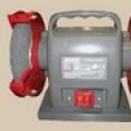
If you go back to the original. One of the properties of the radiant current was demonstrated by Nikola Tesla on the device - a step-up transformer, a capacitor, a spark gap connected to a copper U-shaped bus. Incandescent lamps are placed on a short-circuited bus. According to classical ideas, incandescent lamps should not burn. Electric current should go along the line with the least resistance, that is, along the copper bus.
A stand was assembled to reproduce the experiment. Step-up transformer 220V-10000V 50Hz type TG1020K-U2. In all patents, N. Tesla recommends using a positive (unipolar), pulsating voltage as a power source. A diode is installed at the output of the high-voltage transformer, which smooths out negative voltage ripples. At the start of charging the capacitor, the current flowing through the diode is comparable to a short circuit, so a 50K resistor is connected in series to prevent diode failure. Capacitors 0.01uF 16KV, connected in series.
In the photo, instead of a copper bus, a solenoid is shown wound with a copper tube with a diameter of 5 mm. The contact of the incandescent bulb 12V 21/5W is connected to the fifth turn of the solenoid. The fifth turn of the solenoid (yellow wire), is experimentally chosen so that the incandescent lamp does not burn out.
It can be assumed that the fact of the presence of a solenoid misleads many researchers who are trying to repeat the devices of Donald Smith (the American inventor of CE devices). burns out when moving closer to the ends of the copper bus. Thus, the mathematical calculations used by the American researcher are too simplified and do not describe the processes occurring in the solenoid. The distance of the spark gap of the spark gap does not significantly affect the brightness of the glow of the electric lamp, but it does affect the growth of the potential. Between the contacts of the electric lamp, on which the tungsten filament is fixed, a high-voltage breakdown occurs.
A logical continuation of the solenoid as the primary winding is the classic version of the N. Tesla transformer.
What kind of current and what are its characteristics in the area between the spark gap and the capacitor plate. That is, in a copper bus in the scheme proposed by N. Tesla.
If the length of the bus is about 20-30 cm, then the electric lamp fixed at the ends of the copper bus does not light. If the tire size is increased to one and a half meters, the light starts to burn, the tungsten filament heats up and glows with the usual bright white light. On the spiral of the lamp (between the turns of the tungsten filament) there is a bluish flame. With significant "currents" due to an increase in the length of the copper bus, the temperature increases, the lamp darkens, the tungsten filament burns out pointwise. The current of electrons in the circuit stops, an energy substance of a cold, blue color appears in the area of tungsten burnout:
In the experiment, a step-up transformer was used - 10KV, taking into account the diode, the maximum voltage will be 14KV. Logically, the maximum potential of the entire circuit should not exceed this value. So it is, but only in the arrester, where a spark of the order of one and a half centimeters occurs. A weak high-voltage breakdown in sections of a copper bus of two or more centimeters indicates the presence of a potential of more than 14 kV. The maximum potential in the N. Tesla circuit is at the light bulb, which is closer to the spark gap.
The capacitor starts to charge. On the spark gap, the potential rises, a breakdown occurs. A spark causes the appearance of an electromotive force of a certain power. Power is the product of current and voltage. 12 volts 10 amps (thick wire) is the same as 1200 volts 0.1 amps (thin wire). The difference is that fewer electrons are needed to transfer more potential. It takes time to give a significant number of "slow" electrons in the acceleration copper bus (higher current). In this section of the circuit, redistribution occurs - a longitudinal wave of potential increase occurs with a slight increase in current. A potential difference is formed on two different sections of the copper bus. This potential difference causes the glow of the incandescent lamp. On the copper bus, there is a skin effect (the movement of electrons along the surface of the conductor) and a significant potential, greater than the charge of the capacitor.
Electric current is due to the presence of mobile electrons in the crystal lattices of metals, moving under the action of an electric field. In tungsten, from which the filament of an incandescent lamp is made, free electrons are less mobile than in silver, copper or aluminum. Therefore, the movement of the surface layer of electrons of a tungsten filament causes the glow of an incandescent lamp. The tungsten filament of the incandescent lamp is broken, the electrons overcome the potential exit barrier from the metal, and electron emission occurs. The electrons are located in the region of the rupture of the tungsten filament. The energy substance of blue color is the consequence and at the same time the cause of maintaining the current in the circuit.
It is premature to talk about the full correspondence of the received current with the radiant current described by N. Tesla. N. Tesla points out that the electric lamps connected to the copper bus did not heat up. In the experiment carried out, electric lamps heat up. This indicates the movement of electrons in a tungsten filament. In the experiment, it is necessary to achieve a complete absence of electric current in the circuit: Longitudinal wave of growth of the potential of a wide frequency spectrum of a spark without a current component.
Capacitor charge.
The photo shows the possibility of charging high-voltage capacitors. The charge is carried out using an electrostatic electricity transformer Tesla. The scheme and principles of removal are described in the section on energy removal.
A video demonstrating the charge of a 4Mkf capacitor can be viewed at the link:
An arrester, four capacitors KVI-3 10KV 2200PF and two capacitors with a capacity of 50MKF 1000V. included in series. In the arrester there is a constant spark discharge of satistic electricity. The arrester is assembled from the terminals of a magnetic starter and has a higher resistance than copper wire. The size of the spark gap of the arrester is 0.8-0.9 mm. The gap between the contacts of the arrester based on copper wire connected to capacitors is 0.1 mm or less. There is no spark discharge of static electricity between the contacts of the copper wire, although the spark gap is smaller than in the main spark gap.
Capacitors are charged to voltages of more than 1000V, it is not technically possible to estimate the voltage value. It should be noted that when the capacitor is not fully charged, for example, up to 200V, the tester shows voltage fluctuations from 150V to 200V or more volts.
When the charge is accumulated, the capacitors are charged to voltages of more than 1000V, a breakdown occurs in the gap set by the copper wire connected to the capacitor terminals. The breakdown is accompanied by a flash and a loud explosion.
When the circuit is turned on, a high voltage immediately appears and begins to grow at the terminals of the capacitor, and then the capacitor is charged. The fact that the capacitor is charged can be determined by the decrease and subsequent termination of the electrostatic spark in the spark gap.
If you remove an additional spark gap from a copper wire connected to high-voltage capacitors, flashes occur in the main spark gap.
The capacitor used in the video, MBGCH-1 4 microfarads * 500V, after 10 minutes of continuous operation, swelled and failed, which was preceded by oil gurgling.
During the operation of the circuit, electrostatic electricity is present in all areas, as evidenced by the glow of a neon light bulb.
If you charge high-capacity capacitors without a spark gap, the rectifier diodes will fail when the capacitors are discharged.
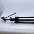
Wireless power transmission.
Both solenoids are wound on a PVC pipe with an outer diameter of 50 mm. The horizontal solionoid (transmitter) is wound with a 0.18 mm wire, length 200 mm, estimated wire length 174.53 m. The vertical solenoid (receiver) is wound with a 0.1 mm wire, length 280 mm, estimated wire length 439.82 m.
The current consumption of the circuit is less than one ampere. Electric lamp 12 volts 21 watts. The brightness of the lamp is about 30% compared to direct connection to the battery.
The increase in the brightness of the lamp, in addition to the perpendicular placement of the solenoids, is affected by the relative position of the conductors - the end of the transmitter solenoid (red electrical tape) and the beginning of the receiver solenoid (black electrical tape). With their close, parallel placement, the brightness of the lamp increases.
The charge of capacitors in the previously considered circuit is possible through an intermediary coil without a direct connection of the pickup unit (high-voltage capacitor and rectifier diodes) with a Tesla transformer. The efficiency of wireless power transmission is about 80-90% in comparison with the direct connection of the pickup unit to the transmitter solenoid. The photo shows the most efficient arrangement of the solenoids relative to each other. Since the arrangement of the solenoids is perpendicular, the transfer of energy through a magnetic field is impossible according to classical concepts. It is possible to visually assess the energy of the process by watching the film:
The upper end of the receiver solenoid is connected to the KTs109A rectifiers, the lower end is not connected to anything. With the circuit running, there is a slight spark at the bottom of the receiver solenoid. The upper end of the transmitter solenoid is in the air, not connected to anything.
Consumption current 1A. As an intermediary coil, solenoids wound with a wire of 0.1 mm, length 200 and 160 mm were tested. The capacitor is not charged to the voltage necessary for the breakdown of the arrester. The receiver solenoid shown in the photo gives the best result. Ferrite fillers were not used in the transmitter and receiver.
Sincerely, A. Mishchuk.
This article will consider the creation of a miniature Tesla coil on a single transistor, or the so-called Brovin's kacher. The bottom line is that in the Tesla coil, a high-frequency alternating voltage is supplied to the primary winding, and in the Brovin coil, the collector current of the transistor feeds the primary winding of the coil. Vladimir Ilyich Brovin found out that it was with such a generator circuit that a high voltage would appear on the collector, and, based on this, he obtained a new way to control the transistor. Therefore, the device is called "Kacher" Brovin (after the name of the author and from the abbreviation of the name reactivity pump).
This device is a generator of high frequency and high voltage, which makes it possible to see the corona discharge. In addition, a sufficiently strong electromagnetic field arises around a working Kacher, which can affect the operation of electronic equipment, lighting lamps, and the like. Initially, Tesla planned to use such devices for wireless power transmission over long distances, but either he faced problems with efficiency, payback, insufficient funding or some other unknown reasons, but at the moment such devices are widely used only as a teaching aid or a toy. .
Materials:
Wire thickness 0.01mm
-wire with a cross section of 2-4 mm
-transistor
-dvd disc
-glue
-discharge lamp
-radiator
-pipe
Description of device creation.
After we figured out what kind of device it was and for what purposes it was assembled by the author, I propose to consider the diagram of this device, which is located below.

As you can see, the scheme of Kacher's device is quite simple, it took the author only 10-15 minutes to solder such a scheme. But he decided to modernize it a bit. So, for example, instead of a choke, a 12 V DC source is also installed, as well as an electrolytic capacitor, the capacitance of which must be at least 1000 μF, and the larger it is, the better.

In order to avoid overheating of the transistor, it is best to place it on a radiator, through which excess heat will be given off. Accordingly, the larger the radiator, the more efficient the cooling will be.

The most routine and probably the most difficult part of the job is winding the L2 coil. It is best to wind the coil with the thinnest possible wire, about 0.01 mm or slightly thicker.

The thinner the wire that is used to wind the coil, the more efficient the device will work. It is necessary to wind the wire on a plastic cylinder, the author used the case from the marker. Accuracy and accuracy are very important in this process. The winding of the wire should take place tightly coil to coil in one layer. If you haven’t noticed a gap in the winding, you will have to rewind the coil again, or you can try to smear the gap with glue.

Next, the marker with the winding must be fixed to the stand. As a rack, the author used a regular dvd-disk. After the marker has been glued and fixed on an impromptu stand, you can start creating the primary winding. The winding L1 must be made of a wire of a very large cross section, approximately 2-4 mm. Moreover, five turns made with such a wire will be quite enough. For ease of winding, the author recommends taking a pipe with a diameter of 2-2.5 times the diameter of the marker.


In order for the lower tap from the marker, going to the transistor, not to touch the secondary winding in any way, it is better to put it under the disk.
If everything is done correctly and without errors, the circuit will function immediately without any additional modifications. It is best to check the operation of the device using a fluorescent lamp, when the device is connected correctly, it will glow when it falls within the range of the device. If nothing happens, then the author advises to check if the thick wire touches the marker, and it may be worth swapping the ends of the L1 winding.


As already mentioned, a correctly assembled circuit of the device will allow you to observe the glow of gas discharge lamps in the field of action. Ordinary incandescent lamps will also show an interesting effect of the so-called glow discharge, similar to a plasma ball. As a result, for a couple of hundred rubles, you can get a very spectacular and beautiful toy, for a very small cost. All used parts can be found at home and bought in shops in the city. The author assures that no more than 200 rubles were spent on everything.


It is worth recalling that despite its small size, the kacher has a strong electromagnetic field, and, therefore, is able to have a negative effect on the human body during prolonged interaction. Therefore, in order to avoid the appearance of headaches or aching pain in the muscles, you should not spend too much time working with the kacher.
A strong electromagnetic field can affect the nervous system, and discharges, due to their high frequency, can leave a burn (although you may not feel pain).
THEREFORE, IT IS VERY IMPORTANT TO FOLLOW THE SAFETY PRECAUTIONS WHEN WORKING WITH THIS DEVICE.
Hello. Today I will talk about a miniature coil (transformer) Tesla.
I must say right away that the toy is extremely interesting. I myself hatched plans for its assembly, but it turns out this business has already been put on stream.
In the review, testing, various experiments, as well as a small revision.
So I ask...
About Nikola Tesla there are different opinions. For some, this is almost the god of electricity, the conqueror of free energy and the inventor of the perpetual motion machine. Others consider him a great mystifier, a skilled illusionist and a lover of sensations. Both positions can be questioned, but Tesla's enormous contribution to science cannot be denied. After all, he invented such things, without which it is impossible to imagine our existence today, for example: alternating current, alternator, asynchronous electric motor, radio(yes, yes, it was N. Tesla who first invented the radio, and not Popov and Marconi), remote control and etc.
One of his inventions was the resonant transformer, which produced high voltage at high frequency. This transformer bears the name of the creator - Nikola Tesla.
Protozoa Tesla transformer consists of two coils - primary and secondary, as well as an electrical circuit that creates high-frequency oscillations.
The primary coil usually contains several turns of large diameter wire or copper tube, and the secondary about 1000 turns of smaller diameter wire. Unlike conventional transformers, there is no ferromagnetic core here. Thus, the mutual inductance between the two coils is much less than that of transformers with a ferromagnetic core.
In the original, a gas discharger was used in the generator circuit. Now the so-called Brovin's kacher is most often used.
Kacher Brovina- a kind of generator on a single transistor, supposedly operating in an abnormal mode for conventional transistors, and demonstrating mysterious properties that go back to Tesla's research and do not fit into modern theories of electromagnetism.
Apparently, a kacher is a semiconductor spark gap (by analogy with a Tesla spark gap), in which an electric current discharge passes in a transistor crystal without the formation of a plasma (electric arc). In this case, the transistor crystal after its breakdown is completely restored (because this is a reversible avalanche breakdown, in contrast to thermal breakdown, which is irreversible for a semiconductor). But to prove this mode of operation of the transistor in the quality, only indirect statements are given: no one except Brovin himself studied the operation of the transistor in the quality in detail, and these are only his assumptions. For example, as a confirmation of the “kacherny” mode, Brovin cites the following fact: what polarity do not connect an oscilloscope to the kacher, the polarity of the pulses that it shows is still positive
Enough words, it's time to move on to the hero of the review.
The packaging is the most ascetic - polyethylene foam and adhesive tape. I did not take a photo, but the unpacking process is in the video at the end of the review.
Equipment:
The kit consists of:- power supply for 24V 2A;
- adapter for euro plug;
- 2 neon bulbs;
- Tesla coils (transformer) with a generator.


Tesla transformer:
The dimensions of the entire product are very modest: 50x50x70 mm.


 There are several differences from the original Tesla coil: the primary (with a small number of turns) winding must be outside the secondary, and not vice versa, as here. Also, the secondary winding must contain a sufficiently large number of turns, at least 1000, but here there are about 250 turns in total.
 The circuit is quite simple: a resistor, a capacitor, an LED, a transistor, and the Tesla transformer itself.
 This is a slightly modified kacher Brovin. In the original, Brovin's kacher has 2 resistors from the base of the transistor. Here one of the resistors is replaced by an LED switched on in reverse bias.
 Testing:
We turn on and observe the glow of a high-voltage discharge on the free contact of the Tesla coil. We can also see the glow of neon lamps from the kit, and gas-discharge "energy saving". Yes, for those who are not in the know, the lamps glow just like that, without being connected to anything, just near the coil.

 Glow can be observed even with a faulty incandescent lamp
  True, in the process of experimenting, the bulb of the lamp burst.
 A high-voltage discharge easily ignites a match:
 The match is easily ignited from the reverse side:
To take an oscillogram of the consumption current, I installed a 2-watt resistor with a resistance of 4.7 ohms in the power circuit break. Here's what happened:

 In the first screenshot, the transformer is working without load, in the second, an energy-saving lamp is brought up. It can be seen that the total current consumption does not change, which cannot be said about the oscillation frequency.
 I marked the zero potential and the midpoint of the variable component with the V2 marker, for a total of 1.7 volts across a 4.7 Ohm resistor, i.e. average current consumption is
0.36A. And the power consumption is about 8.5W.
Refinement:
A clear design flaw is a very small heatsink. A few minutes of operation of the device is enough to heat the radiator to 90 degrees.To improve the situation, a larger heatsink from the video card was used. The transistor was moved down, and the LED was moved to the top of the board.
 With this radiator, the maximum temperature dropped to 60-65 degrees.
 Video version of the review:
The video version contains unpacking, experiments with different lamps, burning matches, paper, burning glass, as well as "electronic swings". Happy viewing.Results:
I'll start with the cons: the size of the radiator is incorrectly selected - it is too small, so you can turn on the transformer for literally a few minutes, otherwise you can burn the transistor. Or you need to immediately increase the radiator.Pros: everything else, some solid pluses, from the "Wow" effect, to the awakening of interest in physics in children.
I definitely recommend buying.
The product was provided for writing a review by the store. The review is published in accordance with clause 18 of the Site Rules.