The router is used to connect several devices to the Internet, a computer, laptop and others, via wired or wireless technology and create a local network between these devices. At the same time, the router implements a barrier between the local network it created and the Internet. Basically, routers work using NAT - Network Address Translation. Sometimes providers provide routers along with the connection, the router can be inside a DSL modem or cable, or purchased separately. But, like any electronic device, routers can fail and many malfunctions can be fixed at home on your own. Consider some common router malfunctions and methods for their elimination, d link router repair.
Most often, the following reasons lead to router malfunctions:
- large voltage surges in the network,
- router overheating,
- router software failures (firmware failures),
- high-frequency interference of electromagnetic radiation during a thunderstorm (in this case, the wan port most often burns out if the provider does not put lightning protection on its cable),
- human factor.
If the router malfunctions, it can lose data packets, work on the Internet and local network is disrupted, firmware is lost, the router can turn off, flash all the indicators.
Solving a problem associated with the inability to enter the router settings at its network address 192.168.0.1
If, after typing the network address of the router in the address bar, the router settings page does not open, then to eliminate this malfunction, you should perform the following operations:
- First, check that you have set the network card settings to automatically obtain an IP address and a DNS address (a direct connection to the router is used).

- If the network card settings are correct, then you need to use the Run command (press the Win + R key combination), then type - cmd and press enter. Now at the command line you need to enter ipconfig.

command line "ipconfig"
In the displayed settings, you need to see what value is opposite the inscription - Main Gateway. This address is used to enter the router settings. If the value of this address does not match the standard value, then the router may have been configured for a specific network with its own requirements. In this case, you need to reset this value to the factory settings. Sometimes in this field there may be no address value at all, and you also need to reset the router. To reset the router, you need to press and hold the Reset button on the router for a while. Usually five or ten seconds is enough. The button hole is narrow enough that you can use a ballpoint pen, needle, or paperclip to press it.

If resetting your router doesn't help, unplugging your ISP cable from your router may help. Pull out the provider cable from the router connector and configure the router without the cable connected. After that, you can reconnect the cable to the router.
Also check the firmware version installed in the router. Check the manufacturer's website for the latest firmware and update it if necessary. You can also check your network card drivers on your computer and reinstall them if necessary.
If the router settings are not saved
To troubleshoot a problem with not saving the router settings or if it is impossible to restore the settings from a separate file, you can try to carry out these operations by opening another browser. This method can help with other router malfunctions.
Computer (laptop, etc.) does not see the WiFi network
There can be many reasons for such a malfunction, and all of them are approximately equally common. Consider the main possible reasons.
If the network of your router is not displayed on the laptop in the list of available networks, then you need to check that the wireless network module is enabled. You can do this by looking at the adapter settings in the Network and Sharing Center on your laptop. The wireless connection must be enabled. In the off state, it will be grayed out and you will need to turn on the wireless connection. If you cannot turn it on, then you need to check if your laptop has a Wi-Fi switch and turn it on.
If, despite the fact that the wireless connection remains on, but shows the status - No connection, then you should check whether the correct drivers are installed for the Wi-Fi adapter and install them if necessary. Drivers must be downloaded from the manufacturer's website. This avoids potential driver incompatibility issues.
In addition, you can try to go to the router menu and change the value for the settings there and change the b / g / n parameter to b / g. If this change helped, then the 802.11n standard is not supported. You can also see in the same settings how the wireless network channel is specified, and if it is there - Automatically, then select the channel from the list.
Other malfunctions
If you often experience disconnections during work, it is recommended to update the firmware of the router. In many cases, this procedure helps to solve the problem.
Sometimes, when working with some Internet providers, to access local resources (torrent trackers, game servers), you need to configure static routes in the router settings. Such settings can be searched on the forums of the provider that provides you with the Internet.
Router power supply failures
Surely, many have already encountered the fact that the weakest point of many routers is their power supplies. They often break due to large voltage drops in the mains and failure of individual elements as a result of long work.
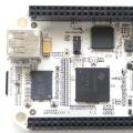
Defective or low-quality elements, a scheme that is not designed for a certain margin, can also lead to breakdowns. There are some typical power supply failures. In this article, we will consider repairing the power supply for the D-Link router. Power supplies such as JTA0302D-E and the like are used for Asus and D-Link routers, designed for an output voltage of 5V and a maximum current of 2-3 A. The appearance of such power supplies can be seen in the figure below.

If we consider the circuit and design of similar power supplies, then this is a circuit of conventional switching single-cycle power supplies. In such circuits, a PWM controller is used to control the operation of a field-effect transistor, which is connected to its output. As a result, the voltage is lowered to the desired value and rectified, and it is supplied to the output. A schematic diagram of such a power supply can be seen in the figure below. In this scheme, depending on the model of the power supply, there may be some minor changes regarding the ratings of individual components. The power supply outputs 5 volts. This voltage should not drop significantly under load (when the router is on).
To repair the power supply, you may need to use a soldering iron, solder, a multimeter, a knife and electrical tape. To open the plastic case of the power supply, you need to cut the glued seam of the case. This operation can be done with a knife, but it is more convenient to use a small drill for these purposes.
If you look at the power supply circuit in Fig. 2, you can see that a 2 amp fuse, a choke, a thermistor and a rectifier bridge of four 1N4007 diodes are installed at the input. If there is a large power surge in the network, then all these elements can burn out. They can be easily checked with a multimeter by measuring their resistance. To smooth the rectified voltage at the output, a high-capacity capacitor - C1 (22 or 33 microfarads) is placed after the diode bridge. This capacitor should be 400 V, no less. If it is out of order, then this can be determined by its appearance, it swells up.
In addition, the positive voltage from the diode bridge is applied to the PWM chip, in this case the UC3843B. This microcircuit is used to control the opening and closing of the P4NK60Z field effect transistor. Often the power circuit of this microcircuit contains a malfunction. This circuit has an electrolytic capacitor C6 and a zener diode ZD1, which is rated for a voltage of 20 volts. This capacitor must be of a certain capacity so that during operation the voltage supply to the microcircuit is always within the permissible operating limits. Therefore, the recommended capacitance is 100uF. If the capacitor is dry, then the capacitance will not be enough to start the microcircuit,
It is quite difficult to determine such an inoperable capacitor by external signs. The small size does not allow you to notice some bulge on its cover. It is possible to measure the capacitance of a capacitor, but often with normal capacitance there is a strong drop in ESR. To check the ESR, special measuring instruments are needed; this cannot be checked with a conventional multimeter or tester.

With voltage drops, the zener diode ZD1 may fail. This can be seen from the darkened (charred) body of the zener diode.
In rare cases, the P4NK60Z field worker may fail. This transistor is supplied with a voltage of 13-15V. from the PWM output. The performance of the field effect transistor can be checked with a multimeter (tester) switched to the diode test mode. On the drain-source channel, the voltage drop is 0.6-0.8 V.
If the voltage at the output of the power supply is 5 V, and when the load is connected, it drops to a value of approximately 2 V., then the electrolytic capacitors at the output of the power supply (C9 and C11) are most likely dried up. To eliminate this malfunction, it is necessary to replace the dried-up electrolytic capacitors with working ones with the same characteristics.
In the general case, the main repair steps can be distinguished. If there is no voltage at the output of the power supply, then it is necessary to check for breakdown by measuring the resistance F1, TR, the rectifier bridge. To provide some start-up margin, it is desirable to use the capacitance of capacitor C6 10 uF and rated for 50v, and not 47 uF and 25v. as usual in the scheme.
In cases where the output voltage drops, unstable operation of the power supply is observed, it is necessary first of all to replace the electrolytic capacitors C1, C9, C10, C11.
In addition, you can recommend a few recommendations to improve the performance of the power supply. At the output of the power supply, a resistor with a resistance of 220 Ohm 0.125w is usually installed, filled with a special sealant. This resistor operates at extreme values and therefore gets very hot. Heating causes the capacitor C9 to dry out. Instead of a 220 ohm resistor, it is advisable to put a 300 ohm resistor and a power dissipation of 0.5 watts. If a 10v capacitor C9 is installed in the circuit, then it is better to put the same one instead, but designed for 16v.
After repair, the body needs to be assembled. But you can not glue it, but fasten the two halves, for example, with a screed, so that in the future, if repair is necessary, it can be easily disassembled again.
DSL-2500U. The owner of this modem complained about the constant dumps of the Internet, if not at all connection failures. And indeed, turning on the modem, I found that the modem was not available even via Ethernet, although the lights blinked as expected.
First, we determine whether the 5V power supply is to blame. We measure the voltage with a multimeter - deviations are allowed plus or minus 10%. If there is a suspicion of a power supply, then carefully disassemble it and change swollen capacitors. Usually this C9, C10, sometimes C3. If the power supply is beyond suspicion, then we disassemble the router. Loosen four screws under glued legs.
Replacing capacitors in the D-link DSL-2500U modem
Under the cover of the router we see an electronic board with swollen capacitors. Capacitors usually overheat and lose capacitance C8 - 470uF x 16V, C14 - 100uF x 16V, C32 - 470uF x 16V, C111 - 470uF x 16V. We change them to capacitors of the same or larger capacity. 
Capacitor C14 is better change to 220uF.  As a result, the repair was successfully carried out modem D-link DSL-2500U - it began to work stably. It seems that the power ripple due to the low filter capacitance overlaps the data signals and breaks the synchronization. Hence the loss of communication and unstable operation of the modem.
Other malfunctions of the D-link DSL-2500U modem
Also, sometimes, the microcircuit fails. U2 Broadcom 6301KSG. Found a solution to this problem. The source states that the chip can be replaced by AD45048.
Which in turn is quite simple replaced by assembly on your favorite KT315G and MLT-0.125 430 Ohm resistors. True, due to the spread in the current transfer coefficient, it is necessary to select resistors for a stable Internet speed. Also transistors can replace with C945, and resistors can be selected up to 20 kOhm. 
Among other frequent malfunctions of D-link modems, there is often a breakdown of the external power supply. In this case, communication with the network may also be lost and the modem itself may periodically fall off. In this case, the repair will consist in replacing the filtering electrolytic capacitors in the power supply.
This completes the note about the repair of the D-link modem DSL-2500U. I hope that your modem will work stably for many years.
Your question:
How to repair USB Yota modem?
Master's response:
Manufacturers of Yota modems, and many users, argue that this USB modem cannot fail in principle - simply because there is nothing to break there. However, practice sometimes refutes this point of view. So if the owner, for example, uses a modem in a car, then the modem can escape from any almost inattentive gesture. Result: by itself - a USB connector, and the modem - by itself. The situation is not the most pleasant, agree?
If, to a lesser or greater extent, you understand the technical intricacies, then you can try to repair the Yota modem yourself. To describe the process briefly, let's say that it consists of a disassembly modem, soldering the necessary elements and assembling all the parts in place. The USB modem should be disassembled very carefully, taking into account the location of the components of the “vital” device. In order to get close to the cable, we slightly press on the modem cover from the back side (where the Yota icon is) and move it towards the USB connector. A plastic plate is fixed on the latches under the cover, which must also be removed. Next, we need to unscrew the pressure plate that secures the USB connector to the case. We remove the board and the printed circuit board from the case with the details of the modem. Disconnect the USB cable from the board. We take out the case of the USB connector, perpendicularly turn the modem itself and carefully squeeze the USB case out of the modem. Next comes the disassembly of the USB connector, which must be carefully opened along the seam.
During the soldering process, you need to solder the wires from the USB case to the appropriate places on the modem board. It is better to do this with a small soldering iron and with the help of a magnifying glass. We check this way: we install the cable into the modem board, and the connector into the computer's USB port.
Before assembly, it is necessary to fix the USB connector in the case: this can be done with glue (not the most effective option), but it is better to straighten a paper clip, make a hole with a soldering iron in one of the halves of the USB connector case and install a paper clip instead of the factory rod. Then you can assemble the modem and case back.
True, in the absence of appropriate devices, and even more so, dexterity and abilities, it is better not to take on the repair of an independent USB modem. You can always contact a service center at least inexpensive, where they will do everything for you as it should be. Otherwise, you run the risk of “killing” your modem completely, and without the possibility of returning it under warranty or exchanging it.
Not sure how to fix a broken modem? You will learn about this from this article. Repairing a modem is actually quite a difficult task. Some users make a big mistake by underestimating the difficulty of this action. Probably my advice may seem unusual, but it makes sense to ask yourself: is it worth repairing a failed modem at all? Maybe it would make more sense to buy a new one? I personally tend to think it makes sense to ask how much a new modem costs. To do this, simply make the necessary request to google. First of all, it makes sense to look for a modem repair specialist. This can be done with yahi or mail. ru, newspapers of free announcements. If you can afford the price of repair services, we will consider the issue resolved. If not, then you will have to repair the modem yourself. If you decide to repair it yourself, then first it makes sense to learn how to repair the modem. To do this, you can use some kind of search engine, or review the issues of the magazines "Skillful Master", "Master-Lomaster", "Young Technician" and the like, or go to the thematic forum. I hope this article helped you solve the problem. Visit our website often to keep abreast of all current events and useful information.
Copyright (c) 2013, Thematic catalog of articles
Do-it-yourself humidifier repair Would you like to know how to repair a failed humidifier? Here, in general, you will read about this problem in this article. Repairing a humidifier is a tricky business. But …
How to fix a shower cabin You have a shower cabin. She served you for a while. And suddenly, once - and it fails. What to do in this situation? That's it, …
Is the greenhouse out of order? We repair on our own. You have a greenhouse. She served you faithfully for a while. And then suddenly it breaks down. What to do in this situation? …
Good afternoon, dear readers of the blog site. If your Internet cable (twisted pair) was gnawed by a dog or cat, it was transferred by furniture or was damaged in another mechanical way, then it can be restored without loss of aesthetic appearance and functional characteristics. Many, remembering the grandfather's way, in the old fashioned way, resort to twisting the cores and further winding with electrical tape. However, in this way it is not permissible to repair the Internet cable.
This method is well suited for breaking the power cable of devices and devices. Any twisting of the twisted pair cores is additional interference, loss of data packets that you can then feel during operation (speed reduction, communication breaks, etc.). By resorting to twisting, you lose the data transfer rate by an order of magnitude.
This article will describe a method for repairing an Internet cable in the event of a break in the area from the entrance to the apartment to connecting the device. If you have damaged or broken the connector, then you can read about its repair in a separate one.
This situation can also occur with the cable from the antenna. Therefore, I recommend that you read the article dedicated.
Required Tool
To repair a damaged twisted pair, we need a few tools:

Cable stripping and cutting tool (stripper)
The stripper is needed to remove a certain piece of external insulation, as well as cut off the excess length of the wires. A knife can also be used to remove the insulation. However, be extremely careful not to damage the integrity of the cores.


Wire connector (scotchlock)
You need as many scotchlocks as you need to splice.

Connector crimping tool
If there is no such tool, then you can get by with simple pliers. However, as with a knife, you need to be careful, otherwise you can damage or crush the connector.
Internet cable repair (step by step)
To begin with, with the help of a stripper, we remove excess insulation in order to free the cores from it (about 2 centimeters). We untwist twisted pairs, for further simplicity of their installation in the connector.

Now, one by one, we take the cores of the same colors from different pieces of the cable and insert them all the way into the connector holes. Then we snap the scotchlock by pressing two fingers. Using a connector crimping tool, tighten the adhesive tape completely and then the wires will definitely not fall out. This operation must be carried out in turn with all the cores.
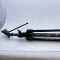
As a result of repairing the Internet wire, you will get a small bundle (as it looks like, see the figure below).

It is recommended to wrap this place with electrical tape for additional protection. But before finishing, I advise you to check your work and make sure that the Internet is working. To do this, you need to insert a compressed twisted pair cable into the connector of the device through which the network is organized (desktop computer, laptop or router). If everything works without failures, then you can safely protect the place of repair of the Internet cable.
I advise you to read the article about. Such a need may arise if you are going to redevelop the premises and the equipment will be moved to another location.
If you liked this article, then subscribe to new ones and use the buttons, please.