Hello! Many people know firsthand about such a measuring device as a pressure gauge. But many find it difficult to imagine the device and the principle of its operation.
The pressure gauge is designed to measure the pressure of a liquid or gas. Moreover, the pressure gauge for measuring the pressure of gas and liquid does not differ structurally from each other. So if you have a manometer somewhere lying around for measuring the pressure of a liquid, then you can safely use it to measure the pressure of a gas and vice versa.
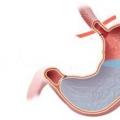
To better understand how the pressure gauge works and works, look at the figure below.
The pressure gauge consists of a housing with a measuring scale, a copper flat tube 1 rolled in the shape of a circle, a fitting 2, a transfer mechanism 3 from the tube to an arrow 4. Using the fitting, the pressure gauge is wrapped in a vessel where the pressure of the medium (gas or liquid) is to be measured.
How does a pressure gauge work
When gas and liquid are supplied under pressure through the nozzle 2, the rolled-up tube 1 will tend to straighten, while the movement of the tube will be transmitted through the transmission mechanism to the arrow 4. It, in turn, will indicate the pressure value, which can be read using a scale. When the pressure decreases, the tube will coagulate again and the arrow will indicate a decrease in pressure.
Electrical contact pressure gauge device
How does an electrical contact pressure gauge work? I guess you guessed it yourself. It does not differ in design from an ordinary pressure gauge, except that it has built-in contacts. There are usually two of them and their position on the manometer scale can be changed.

And if you do not have an electrical contact pressure gauge, but you really need it? What to do then? Then you need to make a homemade electrical contact pressure gauge.
I will tell you how to make a homemade electrical contact pressure gauge. To do this, you will need a simple pressure gauge, two small strips of tin from a tin can, double-sided tape, and two thin wires.
Use a sharp awl to tuck in and remove the large retaining ring. Then remove the glass and then the rubber washer. Drill two holes in the pressure gauge body to route two wires through them.
Cut two strips out of the tin and bend them in the shape of the letter G. Solder a thin insulated wire to the base. From double-sided tape, cut two strips equal in size to the strips and stick it on the strips. Next, glue the obtained contacts to the pressure gauge scale within the specified pressure limits.


Pass the wires through the holes and take them out.

Reinstall the rubber gasket and then the glass. Secure everything with the retaining ring. That's it, the homemade electrical contact pressure gauge is ready. For example, I used this one in a homemade automatic system water supply of a private house.
Electrical contact pressure gauge connection diagram
In order for this pressure gauge to act on any actuator, a special circuit is needed. You can see an example of this scheme in the figure below.

At the minimum pressure of the medium (gas or liquid) in the electrocontact pressure gauge, contacts 1 and 2 will be closed. In this case, the electromagnetic relay K1 will work. It, in turn, with its contacts K1.1 will supply power to the winding of the K3 magnetic starter. With contacts K3.1, it will bypass contacts K1.1, while opening the contacts in the pressure gauge 1 and 2, relay K1 will release its contacts K1.1. But at the same time, the winding K3 of the starter will continue to flow around with current. With its contacts K3.2, the magnetic starter will supply power to the motor M of the pump or compressor.
With a further increase in pressure in the manometer, contacts 1 and 3 close. In this case, the electromagnetic relay K2 will work and its contacts will open the power circuit of the coil K3 of the magnetic starter. In this case, contacts K3.2 will open and the power supply to the motor M will disappear. With a further decrease in pressure and the closure of the contacts of the manometer 1 and 2, the cycle will be repeated.
Compression in the cylinders of an internal combustion engine is measured using a special device called a compression meter. It is a pressure gauge, the main feature of which is the presence of a free valve. Such a pressure gauge does not release the pressure it has received until the maximum value of the value at the top dead center of the cylinder is recorded. Let's try to figure out how to perform and how to make a compressometer with our own hands?

A new high-quality compression meter is quite expensive, and cheap analogs have serious errors that are unacceptable when making accurate measurements. That is why many motorists either go to the station Maintenance and take measurements for just a little money, or they make a compressometer on their own.
This appliance can be made using several parts that can be found in the garages of experienced drivers or at any auto parts store.

List of what you need:
- High pressure hose.
- Nipple (or, as it is also called - spool).
- Pressure gauge.
- Brass adapters already tapped to the required thread.
- A valve used on a wheel chamber from a truck.

The last element must be in good condition and not bent. The diameter is usually 8 millimeters and the end is slightly curved. To use it in the manufacture of a compressometer, it is necessary to align it, leave the threaded part as it is, and the end that was intended for welding into the chamber must be sawed off.
Take a soldering iron and solder the nut onto the cut end of the valve, into which you need to screw it into the pressure gauge. In the resulting tube, you need to twist the spool and insert the hose there. The other end of the hose can be bored to fit a cone that will be inserted into the spark plug hole or secured with a threaded tip.
Use this homemade device very simple: the free end of the hose is inserted or twisted into the spark plug hole, measurements are taken and fixed on paper. To relieve pressure from the pressure gauge, the spool must be tightened.
The thread diameters at the end of the hose must match the spark plug hole exactly. This requirement is associated with increased sealing, which must be at the moment the piston is brought to the top dead center. The measurement accuracy will depend on this requirement, which also does not exclude the occurrence of small errors. Relying entirely on such a device is still not recommended.
In order not to get confused, try to use the units of measurement on the pressure gauge that are indicated by the manufacturer in the technical literature.
Video - How to make a homemade compressometer
This is how a do-it-yourself compressometer is made. Such a device will help you significantly save on professional tools and achieve approximately the same result at minimal cost.

If more recently the car engine was working properly - fuel and oil consumption, as well as power were within the normal range, but then everything became quite the opposite, then it's time to check the pressure in the engine cylinders. As you know, a drop in compression is not the best sign for any engine, since the fuel supplied to it does not burn completely and remains in the form of sediment, which can cause defects both on the cylinders and on the pistons.
How do you know the compression?
As you already understood, in order to measure the compression, you need to purchase a compression meter. After that, it is necessary to perform a number of special actions so that the readings are the most accurate and have minimal deviations.
- The engine must be warmed up to working temperature... This is the very time when he can work at full capacity. Then - drown.
- While the engine is warmed up, it is necessary to turn off the fuel pump. If you have an injection engine, then you just need to disconnect the special plug designed to power the gas pump. In the case of a carburetor, disconnect the hose that goes from the gas line to the fuel pump and the hose on the carburetor float chamber. In order not to burn out - disconnect the terminal from it.
- Remove all spark plugs. Many drivers make the common mistake of twisting only one plug. Doing this is strictly prohibited!
- Now screw the compression gauge into one of the spark plug holes. It is recommended to immediately purchase attachments that are designed to be mounted on different engines.
- Ask your partner to get into the car and press the gas pedal all the way. This is done so that the throttle valve is open. Then, he should turn on the starter for 2 seconds.
- The readings are taken from the compressor and the procedure is applied to the rest of the cylinders. For performance standards, refer to the technical literature for your vehicle.
- The deviations from the norm, obtained during the measurements, can be used to judge the nature and extent of the malfunction that has affected the engine of your car.
Pressure gauges- devices for measuring the pressure of liquids or gases - there are different designs... A simple measurement of air pressure, for example, in a car or bicycle chamber, can be done by hand. Depending on the strength of the spring and the strength of the housing, it can also measure the oil pressure. It is suitable for school experiments in physics lessons. In addition, you can do it with your children.
You will need
- - Disposable syringe
- - Metal spring, the diameter of which is equal to the diameter of the syringe balloon
- - Needle
- - Alcohol or gas burner
- - Glue "Moment"
- - Pliers
- - Nippers
Instructions
Take a disposable syringe and push the plunger out of it to the limit. Cut the piston rod so that a piece is about 1 cm long. Heat the remaining rod piece with a gas torch and melt one end of the coil spring into it.
Insert the plunger back into the syringe balloon so that a small piece of spring remains outside and most of it is inside the balloon.
Warm up the needle and pierce the syringe balloon from the side opposite the tip, near the edge. Using pliers, attach the end of the spring to the needle. Bite off the excess part of the spring. The result is a spring-loaded pressure gauge.
If, instead of a needle, put a rubber tube on the side of the syringe tip and connect it to the container or pipeline in which the pressure is measured, the piston in the cylinder will move relative to the scale on the syringe body, thus indicating the pressure in the line or the container under study.
It is recommended to pre-calibrate the scale against a known pressure source. Snap the scale to the pressure units of the reference source. To do this, pick up the phone from transparent material and fill it with water to a certain height. On the other side, connect the rubber tube with a pressure gauge. Mark the scale for the height of the water column according to Torricelli's law. At the place where the piston moved, make a mark of the pressure obtained. After changing the amount of water in the tube, make the following marks.
They withstood the blow of the elements at the Sayano-Shushenskaya hydroelectric power station. They work on submarines and in mines. They are not taken by tropical humidity and arctic cold. They are real Tomsk manometers.
The former Tomsk manometer plant, and now the Manotom company, managed to provide almost half of the world with its instruments. 70 years of experience, combined with a modernized material base and a team retained at the enterprise, makes it possible to practically work wonders.
The plant produces 500 thousand devices per year. Along with all modifications, the production range includes 10 thousand items. All this is supplied to almost 10 thousand consumers from various fields - from shipbuilding to nuclear power plants.
What is the production of pressure gauges today?
The first step is development
It all starts with the fact that the company receives an order. The first to enter the business are the employees of the design department. They determine how the device should be. If necessary, additional design equipment is ordered, which is produced here, in the tool shop. As soon as the designers create an image of the future device, the production workshops are involved. It is not so rare to develop new modifications of devices - consumers are constantly asking for something new.
Parallel production: from body to spring
From the designers, the development goes into the main production cycle, where 700 people work, and the equipment park is 527 units. The technologies used here, by the way, were developed within the factory walls.
Once development enters the mainstream, the case makers come into play. Each type of pressure gauge and pressure sensor needs its own housing. If the device will be used in not too harsh conditions, then the case can be made of plastic or aluminum. If the pressure gauge is made for the military, or will be used in a "harsh" environment, then the case will be steel. In different cases, the body of the device goes to the workshop for mechanical or galvanic processing. There is also a cold stamping workshop.
In parallel with this, the assembly of the "insides" of the device is going on in other workshops.
The next step is painting the body. Here, too, it was not without know-how. “We have introduced the most advanced powder coating technology today,” says Andrey Metalnikov, Deputy General Director for Production. - The bottom line is that the usual painting from a spray gun with paint by spraying is too expensive. Too much of it simply dissolves in the air without getting on the product. When powder painting, the paint is used 100%, because what did not get on the product returns to the drum again and is not lost. In addition, the coating is stronger and more durable. "
A separate place in the list of subdivisions of the plant is the section of flexible springs. This is where the heart of any pressure gauge is made. The quality of the flexible spring determines the reliability and accuracy of the manometer, its specifications... For "Manotomi" the Ural metal experts have developed a special alloy, from which the springs are made.
The soldering section is the next step. Depending on the need, either soft or hard soldering of the device is performed, and if necessary, then welding, including argon-arc welding.
A separate area is the shop of plastic products. Thanks to modern thermoplastic equipment, parts of polypropylene, polystyrene and any other plastics can be produced here.
Naturally, "Manotom" cannot make the production cycle completely autonomous. For example, the factory receives glass parts and rolled metal from trusted suppliers. But, as far as possible, the plant tries to produce everything necessary in its own workshops. By the way, they work here only with Russian materials, imported parts are not used.
Those of the pressure gauges that need to strengthen the case, being almost ready, are sent to the galvanic workshop. Its presence is a feature of the Tomsk plant, because few enterprises can afford to maintain an electroplating shop. This is a very costly production - and necessary equipment, and by its very nature. After all, electroplating is a variety of chemicals and acids that must be disposed of after technological processes. And here they not only maintain such a workshop, but also constantly improve. technological process in him.
The most important element of the pressure gauge production is the workshop in which the transmission mechanism is created. The transmission mechanism is the central element of the pressure gauge, just as important as the spring. The more accurate and thinner the transmission mechanism works, the more accurate the readings of the device. Therefore, the most experienced workers work in the production of transmission mechanisms, and the technological equipment of the workshop meets the most stringent modern requirements.
“We installed the newest equipment in mid-2010. This gave several tangible advantages at once. Firstly, the accuracy of machining parts of the transmission mechanism has increased. It was possible to eliminate roughness, to improve the accuracy of the readings of our products. Secondly, thanks to this, we were able to raise the warranty period of our pressure gauges from one and a half years at once to three - twice, ”explained Andrey Metalnikov. Other suppliers of the Russian pressure gauge market still provide a one and a half year warranty.
The final stage of production is the assembly line. There are four main conveyors. Each serves its own direction: technical devices, thermometers, special devices and electrical contact devices. Here the devices are assembled and undergo final quality control.
Before handing over the products, each workshop in mandatory checks it for compliance with the requirements. The technical control department of the plant puts a stamp on the products and this completes the process of creating a pressure gauge.
In recent years, "Manotom" has been developing the direction service their products. So, customers from the nearest regions can send a broken product to the factory, where specialists will take care of it. In more remote areas and outside of Russia, the plant concludes contracts for the maintenance of its pressure gauges with contractors.
Another new direction in work is the production of so-called "smart" electronic pressure gauges. They not only provide data, but also participate in the process of managing production facilities, replacing the human operator. So far, their share is not so large - only 15-20%. But the volume of production of such pressure gauges is growing all the time.
“Today our devices float not only on all civilian ships, but also on all warships, fly in rockets, and service artillery. The supplies go to the countries of the CIS, Europe, Asia and Africa, ”notes Andrey Metalnikov.
By tradition, a short video about how pressure gauges are made:
Schemes no programs no pressure gauge available
Having smoked a little these topics: Digital pressure gauge
I realized that many of the motorists are not programmers or radio amateurs, and not everyone will be able to assemble this digital pressure gauge. I suggest a simpler digital pressure gauge that almost every car enthusiast can repeat.

Since all of the above listed devices are based on voltage measurement. I decided to make friends with a 24 V voltmeter I have implemented on the MEGA48PA microcontroller and an MM370 0-10kg / cm2 pressure sensor with a resistance of 195 Ohms. Since we have an upper sensor limit of 10kg / cm2, then I applied a voltage of 10V to a voltmeter and measured the voltage at the input of the MEGA48PA 28 leg, it was 0.5V, therefore the measurement limit of 0-10kg / cm2 will correspond to the input of the ADC (28 leg) 0-0, 5B.
Since the resistance of the sensor with increasing pressure decreases from 195 Ohm to 0 Ohm, it is necessary to redo it a little so that the resistance increases with increasing pressure from 0 Ohm to 195 Ohm.
Alteration of the MM370 sensor for a digital pressure gauge.
Before reworking the sensor, the circuit can be drawn like this (decrease in resistance with increasing pressure) 
we need to redo it so that the circuit looks like this (increase in resistance with increasing pressure) 
To do this, it is necessary to flare the sensor, I used side cutters.

Before that, it is necessary to put marks on the cover and the sensor body (then it will be useful during assembly). After disassembling, we see what is inside, namely the measuring element itself and the moving contact. Using a screwdriver, unscrew and remove the measuring element,

it must be turned over 180 degrees, before that the contact has been slightly cut (so that it does not reach the body, I got it) 
Test measurements were made, and a graph was drawn up of the dependence of the resistance of the MM370 on the readings of the pressure gauge.

and a graph is built (almost linear)
Also, my MM370 (BU) had a damaged wire,

connecting the movable contact with the body, I replaced it with a wire from a telephone headset.


We assemble and carefully roll (without using a hammer), you can fix it a little by welding (semi-automatic)
ADJUSTMENT OF THE VOLTMETER
To do this, you need to replace the 28 volt divider (in my case) in the input circuits of the voltmeter

Since we need a voltage limit from 0 to 0.5V, we use a 5V reference voltage source which is located in the voltmeter itself (power supply of the MEGA48PA microcontroller 4 legs) By simple calculations, we need a divider by 10, since the resistance of the MM370 pressure sensor is 195 Ohm, then the resistance for the divider 1.95 kOhm is needed, it is better to put two, one of which is variable, I put two on 1 Kom

Now we have three wires plus + minus power supply and pressure measurement on the voltmeter.

We connect the pressure gauge to the compressor, do the calibration with a variable resistor (for more accurate readings, the calibration must be carried out at the pressure we expect to use)