The red symbol indicates danger.
When the symbol appears:
- Stop.
- Stop the engine.
- Check the faulty function. Seek qualified assistance if necessary.

Red symbols indicate a malfunction of the first priority (danger).
When the red symbol appears, three consecutive warning beeps sound.
The flashing of the symbol continues until the fault has been rectified.
If several malfunctions of the first priority level occur at once, the symbols appear sequentially, with the duration of indication of each of them 2 s.
Brake system malfunction
Repair the brake system failure as soon as possible.
A flashing 0 symbol on the display indicates a malfunction of the brake system.
- Stop.
- Check brake fluid level.
Attention
Cooling system failure
Repair the cooling system problem immediately.
The reason for the flashing of the symbol while driving may be overheating or a drop in the coolant level.
- Stop.
- Stop the engine.
- Check coolant level.
- Top up coolant if necessary.
- Continue driving only after the symbol goes out.
- Seek qualified assistance if necessary.
If the battery discharge warning lamp is additionally lit, the cause may be a broken V-ribbed belt.
Attention. Never open the hood if you see or hear steam or coolant escaping from the engine compartment - risk of burns! Wait until the release of steam or coolant stops.
Carefully. Do not continue driving if the symbol indicates a malfunction of the cooling system - risk of engine damage.
Malfunction in the engine oil pressure system
Repair the fault in the engine oil pressure system immediately.
A flashing symbol on the display indicates that the oil pressure has dropped below normal.
- Stop.
- Stop the engine.
- Check engine oil level.
- Seek qualified assistance if necessary.
Top up motor oil when its level falls below normal.
Normal engine oil level
You must not continue driving if the symbol flashes when normal level oils. Also, do not allow the engine to idle - get qualified help.
Note. The oil pressure indicator lamp is not an indicator of its level in the lubrication system. Therefore, check the oil level regularly, best when refueling.
Tire pressure drop
Reduce air pressure in tires as soon as possible to bring to normal.
The appearance of the symbol indicates a drop in air pressure in the tire of at least one wheel.
- Stop.
- Check pressure/tyres.
- Replace wheel if necessary.
The appearance of the symbol in combination with the additional information REIFENDRUCKE PRUFEN (check tire pressure) may indicate a pressure drop in several tires, including the spare wheel.
The display may also show a yellow symbol. This symbol indicates the need to control the air pressure.
Yellow symbols (vehicles with FIS, standard)
Yellow symbols are warning symbols.

Purpose of yellow symbols:

Yellow characters (cars with FIS, with on-board computer)
Yellow symbols are warning symbols
Purpose of yellow symbols:

Yellow symbols signal a malfunction of the second priority level (warning).
When the yellow symbol appears, one warning tone will sound.
Check the corresponding function as soon as possible.
If several warnings are displayed at the same time, the symbols appear sequentially, for approximately 2 seconds each.
Brake signal failure
Vehicles with FIS and on-board computer
If the BREMSLICHT symbol or display lights up, the following items must be checked and, if necessary, replaced or repaired by Audi:
- incandescent brake lights,
- wiring connections,
- brake light switch.
Malfunction of a low beam, light of headlights of a backing
If the symbol lights up, check the following components:
- low beam incandescent lamps
- reversing headlight bulbs
- wiring connections.
Note. This function is controlled by the fault monitoring system only when the light is on.
Front brake pad wear
If the symbol appears, contact Audi to check the brake pads on the front (and for the safety of the rear) wheels.
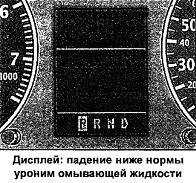
Washer fluid level drop
FIS vehicle with on-board computer
When the symbol appears, it is necessary to add washer fluid to the washer fluid reservoir and the headlight washer.
Low fuel
If this symbol lights up for the first time, it means that about 7-8 liters of fuel are left in the reserve. You need to fill up your car as soon as possible.
Battery voltage abnormal
Car with FIS and on-board computer
If the symbol appears, contact Audi and check the following components:
- v-belt
- voltage regulator
- battery status
The voltage of the on-board network can also be monitored using a voltmeter.
Check engine oil level
When the symbol appears, check the oil level as soon as possible and top up if necessary.
Engine Oil Sensor Malfunction
If the symbol appears, contact Audi to have the oil level sensor checked. Until then, for safety reasons, check the oil level each time the vehicle is refueled.
Car with FIS and on-board computer
The appearance of the symbol means that the actual speed has exceeded the entered speed value. Reduce speed.
Headlamp leveling device malfunction
Vehicles with dynamic headlight beam throw adjustment
The appearance of the symbol indicates a malfunction of the dynamic headlight beam throw adjustment. Have an Audi dealer repair the headlight beam throw adjustment.
Tire pressure drop alarm
Vehicles with a tire pressure monitoring system
If the symbol lights up, it means that the air pressure in the tire needs to be monitored and corrected.
The symbol always appears together with the corresponding wheel letter, eg VR stands for front right wheel.
Speed alarm
Car with FIS and on-board computer
The overspeed alarm allows you to set a speed limit that must not be exceeded.

The overspeed alarm alerts the driver when a pre-set speed is exceeded. As soon as the actual speed exceeds the entered value by about 10 km/h, a warning tone will sound. At the same time, an alarm symbol appears on the display.
The overspeed alarm allows you to program two levels of warning that operate independently of each other and do not perform exactly the same tasks.
Warning level 1: function
Car with FIS and on-board computer
The value of warning level 1 can be changed while driving.
Warning level 1 makes it possible to set a speed limit while driving. The entered speed value is stored in memory until the ignition is turned off, if there has not been a change in speed or cancellation of the entered restriction beforehand.
The signal symbol of the first degree of warning appears on the display when the actual speed exceeds the entered value. The symbol goes out when the speed decreases below the programmed sign.
The symbol also goes out when the entered speed is exceeded by approx. 40 km/h for at least 10 s. However, this does not reset the memory of the entered speed limit.
Warning level 1: programming
Car with FIS and on-board computer
Warning level 1 is programmed with the setting/control button.

Speed Limit Programming
- The vehicle must move at the current speed, which must not be exceeded.
- Press and release the setting/control button.
- Vehicle speed must be over 5 km/h.
- Press the setting button/control button for more than 1 s.
Warning level 2: function
Car with FIS and on-board computer
The value of warning level 2 can only be changed when the ignition is switched off.
Warning level 2 will allow programming and override of the maximum speed limit only when the ignition is off. Programming this warning is recommended when a general reminder is needed for the driver to maintain a certain maximum speed. For example, when driving in a country with a speed limit, the maximum speed when driving with winter tires.
The signal symbol for the second level of warning appears on the display when the actual speed exceeds the entered value. The symbol goes out, in contrast to warning level 1, only when the speed drops below the programmed value.
Warning level 2: programming
Car with FIS and on-board computer
Warning level 2 is programmed and canceled by switches mounted in the wiper handle.

Maximum Speed Programming
- Switch off the ignition.
- Press the setting/control button for at least 2 s. The display shows the currently entered maximum speed threshold or a crossed-out symbol for warning level 2 if maximum speed not previously programmed.
- To change the speed, press the top or bottom side of the function switch mounted in the wiper handle. In this case, there is a gradual (one stage 10 km / h) increase or decrease in values.
- Switch off the ignition.
- Press and release the setting/control button in the instrument cluster. The illumination of the distance meter and digital clock turns on.
- Press the setting/control button for at least 2 s. The currently entered maximum speed threshold appears on the display.
- Press the reset button mounted in the wiper arm B until the crossed-out warning symbol 2 appears on the display.
Dashboard Audi 100/ 100 Avant, S4/ S4 Avant 1. Gear lever 2. Electrically adjustable exterior mirrors 3. Bonnet release handle 4. Signal 5. Diesel engine warm-up 6. Power windows 7. Door handle 8. Handle.. .
 Dashboard Audi A6/ A6 Avant, S6/ S6 Avant 1. Door handle 2. Switch central lock 3. Knurled air control knob 4. Lever switch for direction indicators and dipped beam with a switch for maintaining a constant speed system 5. Switch ...
The prevention At fire of one of the lamps designated by the symbol "STOP", during the movement stop and muffle the engine. Temperature/Coolant Level Brake System Engine Oil Pressure...
 A - front left B - front right C - rear left D - rear right S - fuse button The fuse button (S) can de-energize the rear door windows. ...
 Height adjustment Tilt the steering wheel up or down. Length adjustment Press the steering wheel away from you or pull it towards you. After adjusting, return the lock handle to its original position. ...
 1 - Ignition off / engine off, steering wheel can be locked. 2 - Ignition on, preheating system on (diesel), "on for driving". On vehicles with a fault monitoring system, "BREMSLIGHT" or the symbol appears on the display after the ignition is switched on. Click and...
 1 - Heated driver's seat control 2 - Fog lamps 3 - Rear fog lamp 4 - Heated rear window 5 - Hazard warning lights 6 - Fuel filter (diesel) or coolant level control 7 - Headlight range control 8 - Drive wheel slip control 9 – R...
 A - right turn indicator B - left turn indicator C - high beam D - low beam, light signal Light switch 0 - lighting off 1 - parking lights 2 - headlights Daytime outdoor lighting In some export versions, when the ignition is on, the light ...
 Wiper and washer system 0 - system off 1 - intermittent operation 2 - slow mode 3 - fast mode 4 - start-stop mode 5 - windshield washer Headlight washer When the headlights are on, their washers operate each time the windshield washer is turned on. ...
 A - fan B - temperature controller C - air distributor Normal operation Switch (A) in position II or III. Temperature regulator (B) in the position corresponding to the required heater output. Air outlet (C) in foggy position. ...
Automatic (standard) mode Standard setting for any season: Press the AUTO key. Set the temperature to 22°C. Make changes to the indicated setting only if necessary, depending on individual well-being. Programming...
 A - driver's side B - front passenger's side Press button A or B. The reflective surface of the mirror is set to the desired position by pressing the corresponding side of the large flat button C with arrows printed on it. ...
 A - mirror turn button B - switch button to the right or left mirror or to fold both mirrors 1 - neutral position L - mirror on the driver's side R - mirror on the passenger side 2 - laying both exterior mirrors ...
 0 - close A - raise B - move away Turn the handle to the desired position to raise/remove the panel. Emergency closing of the sunroof If the electric drive fails, the sunroof can be closed manually. Remove the drive cover. The cover comes off at the front. Remove the crank handle from the back of the cover. Spin...
 The car is equipped with an automatic transmission (AKP) with electronic control. P - Parking R - Reverse N - Neutral (Idle) D - Normal driving position 3 - Hilly driving mode 2 - Mountain driving mode 1 - Steep hill driving mode...
1.18 Dynamic Switching Program (DPS)
Early upshifts and late downshifts ensure optimal fuel consumption. The control unit performs automatic program switching. With a restrained driving style, the automation selects an economical shift program. With a temperamental driving style with sharp acceleration and frequent speed changes, using the maximum ...
1.19 Spare or emergency program
VEHICLES WITH A 4-CYLINDER ENGINE In the event of a system malfunction, the automation switches to an emergency or backup version. This is signaled by the glow of all segments on the indicator board at once. Backup program Switching to downshifts and upshifts is carried out automatically as before, only in this case, shocks become more noticeable when shifting ...
 When the ignition is switched on, an indication of the actual position of the control lever appears in the instrument cluster. This illustration shows the "P" position. P - parking lock Driving wheels are blocked by means of kinematic links. The parking lock can only be used after the vehicle has stopped. ...
1.21 Kick-down device
The Kick-down device allows you to realize maximum acceleration. When the accelerator pedal is pressed sharply with the transition of the point of resistance, the automation switches to a lower gear depending on the speed and speed. Shifting to the next higher gear occurs only when the maximum engine speed is reached. ...
Starting the engine The engine can only be started when the control lever is in the "N" or "P" position. Selecting a driving mode Always depress the brake pedal before selecting a driving mode when the vehicle is stationary and the engine is running. Do not depress the accelerator pedal when shifting before the vehicle starts moving. In the event of an...
 1. Coolant temperature gauge 2. Tachometer 3. Ambient temperature 4. Speedometer with odometer/ trip odometer/ interval indicator Maintenance 5. Button for resetting the one-time mileage counter 6. Fuel gauge in the tank ...
1 – temperature of a cooling liquid The index works at the included ignition. However, after switching on, some time must elapse before the pointer is set to the position corresponding to the actual temperature. Cold engine temperature range While the needle is on the left side of the scale, avoid high speeds and ...
Brake system failure Low fluid level in the cooling system or overheating Oil pressure drop below normal When a flashing red symbol appears, three successive warning sounds are heard ...
BREMSLIGHT or brake light failure Low beam or reversing lamp burnt out Brake pad wear Low washer fluid level...
 The function switch (arrow) and the reset button ("Reset") are mounted in the wiper control handle. If the ignition is on, pressing the lower side of the function switch repeatedly will display them in sequence. By pressing the top side of the switch, the f...
1 – driver's seat electric heating switch Switches are made in the form of corrugated handles. With the ignition on, you can use the electric heating of the pillows, backrests of the front and outer rear seats, as well as the steering wheel. The knurled knob (1) can be used to switch on and steplessly adjust the driver's seat heating...
 With this system, within the limits of the capacity of the engine, it is possible to maintain any set speed from about 40 km/h. Thanks to this, it is not necessary to keep your foot on the accelerator pedal, which is especially convenient on long journeys. Warning The cruise control system must not be used at high intensity...
The wiper and washer system only works when the ignition is on. The electric heating of the washer nozzles is switched on when the ignition is switched on, depending on the outside temperature. In frost, before turning on the wiper for the first time, check if the brushes are frozen! Windshield Work in start-stop...
 The air conditioner automatically maintains a uniform microclimate throughout the interior space. To do this, the temperature of the air entering through the supply ducts is automatically changed, as well as its mass flow (air quantity) and the distribution of air flows. If necessary, manual adjustments can be made to this automatic process. ...
 The air supply through the devices intended for this is regulated, depending on the selected control mode, automatically or manually. The illustration shows the air supply devices located on the instrument panel. Through any of them, heated, unheated or cooled fresh air can flow. Supply...
 A - display B - yellow control lamp for programming the start time C - green control lamp for turning on the heater D - heating/ventilation button
1.34 Electronic differential lock (EDS)
EDS works in conjunction with ABS. EDS operates in automatic mode, without the participation of the driver. Using ABS sensors, the device controls the speed of the drive wheels up to a speed of about 40 km/h. The device specifically brakes slipping wheels (for example, on a slippery roadway), and those with better grip receive increased traction. Need to hold...
 5-cylinder diesel engine 1. Terminal (-) for auxiliary cable 2. Battery 3. Terminal (+) for auxiliary cable 4. Engine oil filler hole 5. Engine oil dipstick 6. Brake fluid reservoir 7. Expand...
1.36 Power steering / Servotronic, ride height control
With conventional servo control, the power steering is controlled without electronic control. On vehicles with Servotronic, the electronic governor controls the power steering in response to vehicle speed. In the event of a failure of the Servotronic system, the operation of the power steering is maintained. However, the amplification efficiency...
User manual
A6 devices for a given use case can be programmed in one of four ways to choose from:
- using a PC using the IS-232 module, or the PROG-1 module and
specialized software "Programmer Ah";
- using the PR-1 programming console and the tables corresponding to it
programming;
- using the VPU-A-06 keyboard using the IS-485 module and the corresponding
programming tables;
- using the VPU-A-16 keyboard using the IS-485, KSO-A module and
corresponding programming tables.
To implement the programming of devices, it is necessary to edit a number of groups of parameters allocated to certain program pages. After editing, the changed configuration is written to the instrument's non-volatile memory by writing.
The A6 instrument contains the following program pages:
- "GENERAL" ("PARAMETERS"): the general properties of the device A6 are set, the choice is made
automated security system and type of radio channel;
- "LOOPS": the parameters of each of the alarm loops are determined;
- "ZONES": properties of arming/disarming zones and correspondence of loops to zones are set;
- "ACCESS": properties of access control systems are defined;
- "ACTIVATORS": work parameters are selected external devices(buzzer, SZU, relay);
- "KEYS": user keys ("Master", "GZ", "INSTALLER" and "MASTER") are entered.
Programming the parameters of the A6 device using a PC is one of the most convenient and intuitive ways. This programming option makes it possible to create an archive and store the program settings of each device as files on a PC, which allows you to restore the full configuration of the device at any time on any of the objects. Also, in addition to instrument programming, specialized software makes it possible to monitor devices connected to the network and view all the events occurring in them.
The PR-1 programming console and the VPU-A-06 keyboard are recommended for use when
programming the device or promptly making changes to its program settings directly on the site.
In the case of programming using PR-1, the parameter values are entered in a hexadecimal code into the corresponding memory cells of the remote control, according to the programming table, with the subsequent transfer of the entire program from the PR-1 remote control to the non-volatile memory of the device. Also, the convenience of using the PR-1 programming console lies in the possibility of storing in the non-volatile memory of the PR-1 the electronic keys of the services: "GZ" and "INSTALLER" (keys of the contact method of reading DS1990A, DS1991-DS1996). And, if necessary, prompt transfer of key data codes to
device memory A6.
When programming with VPU-A-06, the program settings of the panel are first read into the keyboard memory and after editing, in accordance with the programming tables, they are entered into the non-volatile memory of the A6 device by recording.
When combining devices "A6" in the ISB "Network A" based on KSO-A, programming the configuration of the devices is possible using the VPU-A-16 keyboard. When using this programming method, the program settings of the panel are read into the KSO-A memory using VPU-A-16, and after programming the device configuration for a given use case, they are entered into the device’s non-volatile memory by writing.
2 DESCRIPTION OF PROGRAMMING DEVICES "A6" ON PC
2.1 Description of software versions "Programmer Ax"
Ax (4.5.2.ХХХ*) Light.exe is a freeware program. Allows for
programming of device configurations "A6" and "A16-512".
Ax (4.5.2.ХХХ*) Full.exe is a commercial version of the program. Allows you to:
- programming of configurations of devices "A6", "A16-512" and KSO-A (controller KSO-
BUT);
- monitoring of up to 32 devices of the A6 series in the network connected to one PC COM port with
display on the monitor screen of service and alarm messages coming from devices with
description of loops, zones, ACS and keys;
- monitoring of up to 32 KSO-A in the network connected to one PC COM port. To controller
KSO-A can be connected up to 32 devices.
*NOTE: XXX software version.
Manufactured by LLC NPK "MIKROFOR" (Russia)
Thermohygrometers IVA-6A and IVA-6N are self-contained portable devices and are designed to measure relative humidity, temperature and atmospheric pressure (optionally) of air in residential, warehouse and industrial premises, as well as in a free atmosphere.Thermohygrometers IVA-6A, IVA-6N consist of an indication unit and a measuring transducer.
In the IVA-6A thermohygrometer, the measuring transducer is connected to the display unit with a flexible cable about 1 meter long, which allows you to control the humidity and air temperature in hard-to-reach places, for example, in ventilation ducts.
In the IVA-6N thermohygrometer, the measuring transducer is installed on the display unit. Thermohygrometer IVA-6N can be placed on the wall using a bracket.
Thermohygrometers can be used:
- for measuring microclimate parameters in museums, archives, libraries, pharmacies, testing laboratories, clean rooms in the pharmaceutical and electronic industries
- for attestation of workplaces in labor protection centers and TsGSEN
- for air humidity control in the printing industry
- to control the storage of products.
Designations of devices IVA-6 when ordering:
- IVA-6A: with a remote probe on a cable without registration of measured values and a channel for measuring atmospheric pressure.
- IVA-6A-D: with a remote probe on a cable without recording measured values, with a channel for measuring atmospheric pressure.
- IVA-6A-KP: with a remote probe on a cable with the registration of measured values on a memory card (microSD), without a channel for measuring atmospheric pressure.
- IVA-6A-KP-D: with a remote probe on a cable with the registration of measured values on a memory card (microSD) and a channel for measuring atmospheric pressure.
- IVA-6N: with built-in probe without registration of measured values and atmospheric pressure measurement channel.
- IVA-6N-D: with a built-in probe without recording measured values, with a channel for measuring atmospheric pressure.
- IVA-6N-KP: with built-in probe with registration of measured values on a memory card (microSD), without a channel for measuring atmospheric pressure.
- IVA-6N-KP-D: with a built-in probe with the registration of measured values on a memory card (microSD) and a channel for measuring atmospheric pressure.
Additional accessories for thermohygrometers IVA-6A and IVA-6N:
| Bag for storage and transportation of thermohygrometers IVA-6A(N) | |
| Bracket for mounting IVA-6A(N) on the wall | |
| Cable KU-1 for using the built-in probe IVA-6N as a remote probe | |
| Mini USB-A cable for reading the data accumulated on the memory card via the USB port and configuration of the thermohygrometer |
|
| Protective cap ZKF-1 made of porous fluoroplastic to protect sensors from dust and aerosols |
The metrological characteristics of the IVA-6A and IVA-6N thermohygrometers are almost the same, except for the temperature measurement range: from -20 to 50°C for the IVA-6N thermohygrometer and from -20 to 60°C for the IVA-6A thermohygrometer, which is caused by permissible operating conditions display block.
When connecting the KU-1 extension cable, all metrological characteristics of the IVA-6N and IVA-6A thermohygrometers become exactly the same.
The liquid-crystal display of thermohygrometers IVA-6A and IVA-6N continuously indicates the current measured values of temperature and relative air humidity. The update period is 60 seconds. When you press any button, the thermohygrometer switches to the "fast" measurement mode and the period for updating the readings on the indicator is 1 s. After 30 s, the display update period returns to 60 seconds.
The time of continuous operation when using alkaline cells with a capacity of 2 Ah and turning on the "fast" measurement mode for no more than 1 hour per day is at least 1 year.
The thermohygrometer calculates the dew point (frost) temperature from the measured temperature and relative humidity values.
At negative temperatures, the device can display the value of relative humidity over water or over ice.
Thermohygrometers IVA-6A, IVA-6N are produced in 2 modifications:
- without atmospheric pressure measurement channel (IVA-6A, IVA-6N, IVA-6A-KP and IVA-6N-KP)
- with a channel for measuring atmospheric pressure (IVA-6A-D, IVA-6N-D, IVA-6A-KP-D and IVA-6N-KP-D)
Atmospheric pressure units are "hPa" (hecta Pascals, 1 hPa = 100 Pa = 0.1 kPa) or "mmHg. Art. " (millimeters of mercury column) are selected by the user when configuring the thermohygrometer via the USB port.
Thermohygrometers IVA-6A, IVA-6N are available in 2 versions:
- with registration of measured values on a microSD memory card and the ability to read the accumulated data via a USB port (IVA-6A-KP and IVA-6N-KP)
- with the function of measured value registration disabled (IVA-6A and IVA-6N)
In thermohygrometers with disabled registration function (IVA-6A, IVA-6N, IVA-6A-D and IVA-6N-D), the registration function can be activated by the user using a key purchased from the device supplier. Activation instructions and a key are supplied on a memory card or sent by e-mail (in this case, the consumer purchases a memory card on their own).
A slot for installing a memory card and a mini USB connector for connecting to a personal computer are located on the upper end of the thermohygrometer display unit.
To register the measured values of relative humidity and temperature in real calendar time mode, the thermohygrometer uses standard removable memory cards microSD. A memory card for instruments with activated data logging is included with the instrument. The program is delivered on the same card datalogger.
The number of records of measured humidity and temperature values is 100,000 per 1 MB of memory card capacity, which ensures continuous data recording for the entire life of the battery pack.
Reading the accumulated data from the thermohygrometer is carried out in two ways:
- from a memory card via a card reader
- via the USB port of the thermohygrometer
Software datalogger provides reading information from a memory card, forms a data archive for each thermohygrometer, creates text and graphic reports.
A memory card can be installed in any thermohygrometer, since at the time of installation a file containing information about the device number is created on it.
The data written to the card is encrypted to prevent the possibility of falsification.
Thermohygrometers IVA-6A and IVA-6N remember the minimum and maximum values of humidity and temperature, the time and date of these events.
For use in low light conditions, the user can turn on the indicator light by pressing the "✱" button. The backlight is turned off by pressing the “✱” button again or automatically after 20 s. The backlight brightness is adjusted when configuring the thermohygrometer via the USB port using the DataLogger software.
Thermohygrometers have sound and visual indication of measured values of relative humidity and temperature going beyond the limits set (using the DataLogger program).
When operating the thermohygrometer in highly polluted conditions, it is recommended to use a protective cap made of porous PTFE to protect the sensors from aerosols, dust and condensate.
The use of a protective cap prevents deterioration of metrological characteristics when the surface of the humidity sensor is contaminated.
Specifications
| Relative humidity measurement range, %RH | 0…98 |
| Permission | 0,1 |
| Limits of permissible basic absolute error of measurements of relative humidity at a temperature of 23°С, %RH | ±2% (in the range 0…90%); ±3% (in the range 90…98%)2 |
| Temperature measurement range, °С | -20…601 |
| Permission | 0,1 |
| Limits of permissible absolute error of temperature measurements, °C | ±0.3 |
| Atmospheric pressure measurement range, hPa | 700…11003 |
| Permission | 0,1 |
| Limits of permissible absolute error of atmospheric pressure measurements, hPa | ±2.5 |
| Time constant: | by relative humidity, min, no more than 2, by temperature, min, no more than 5 |
| Overall dimensions, (L x W x H), mm: | display unit (IVA-6N) 25 x 70 x 135 (25 x 70 x 175); measuring transducer Ø 16 x 165 |
| Weight, kg, no more | 0,4 |
| Nutrition | 3V (2 AA batteries) |
2 metrological characteristics at relative humidity above 90% are provided only for a short-term (no more than 2 hours) stay of the transducer under these conditions.
3 only for thermohygrometers in the corresponding modifications.
No. 46434-11 in the State Register of Measuring Instruments of the Russian Federation