Axle arrangementX, Y, Zdesktop CNC milling and engraving machine:
The Z axis moves the tool (milling cutter) vertically (up and down)
Axis X - moves the carriage Z in the transverse direction (left-right).
Y-axis - moves the movable table (back and forth).
The device of the milling and engraving machine can be found
The composition of the set of CNC machine Modelist2020 and Modelist3030
I A set of milled parts made of 12mm plywood for self-assembly
A set of milled parts for the assembly of a CNC machine with a sliding table consists of:
1) CNC router gantry legs
2) a set of CNC milled parts to assemble the Z axis
3) A set of CNC milled parts to assemble the sliding table
4) a set of milled CNC machine parts for assembling stepper motor supports and spindle mounting
II Set of milling machine mechanics includes:
1. coupling for connecting the stepper motor shaft with the lead screw of the machine - (3 pcs.). The size coupling for machine Modelist2030 with NEMA17 stepper motors - 5x5mm. For Modelist3030 machine with Nema23 stepper motors - 6.35x8mm
2. steel linear guides for CNC machine Modelist3030:
16mm (4pcs) for X and Y axes,
12mm(2pcs) for Z axis
For CNC machine Modelist2020, the diameter of the linear movement guides:
12mm(8pcs) for X, Y and Z axes.
3. linear rolling bearings for milling machine Modelist3030:
Linear bearings LM16UU (8pcs) for X and Y axes,
Linear bearings LM12UU for Z axis.
For CNC milling machine Modelist2020
Linear bearings LM12UU (12pcs) for X, Y and Z axes.
4. lead screws for the milling machine Modelist2020 - M12 (pitch 1.75mm) - (3pcs) with processing under d=5mm from one end and under d=8mm from the other.
For milling machine Modelist3030 - TR12x3 trapezoidal screws (pitch 3mm) - (3 pcs.) with end processing under d=8mm.
5. radial bearings for fastening the lead screws - (4pcs) one bearing in an aluminum block for the Z axis.
6. running nuts made of graphite-filled caprolon for the X, Y and Z axes (- 3 pcs.)
III CNC milling machine electronics set:
1. For CNC machine Modelist2020: NEMA17 stepper motors 17HS8401(size 42x48mm, torque 52N.cm , current 1.8A, phase resistance 1.8Ω, inductance 3.2mH, shaft diameter 5mm)- 3 pcs.
For CNC machine Modelist3030: stepper motors 23HS5630 (size 57x56mm, torque 12.6kg*cm, current 3.0A, phase resistance 0.8Ω, inductance 2.4mH, shaft diameter 6.35mm)- 3 pcs.
2. CNC stepper motor controller based on specialized Toshiba TV6560 microstepping drivers in a closed aluminum case
3. power supply 24 V 6.5 A for CNC machine Modelist2020 and 24V 10.5A for CNC machine Modelist3030
4. set of connecting wires
The assembly sequence of the CNC milling machine with a movable table.
The linear movement system of any machine tool consists of two parts: a linear bushing is an element that moves and a fixed element of the system - a linear guide or shaft (linear support). Linear bearings can be different types: bushing, split bushing, aluminum shell bushing for easy fastening, ball carriage, roller carriage, whose main function is to bear the load, ensuring stable and accurate movement. The use of linear bearings (rolling friction) instead of plain bushings can significantly reduce friction and use the full power of stepper motors for useful work cutting.
Picture 1
1 Lubricate the linear bearings of the system linear movement of the milling machine with special grease (you can use Litol-24 (sold in auto parts stores)).
2 Assembling the Z axis of the CNC milling machine.
The assembly of the Z axis is described in the instruction ""
3 CNC milling table assembly, Y axis
3.1 Details for assembling the portal, figure 2.
1) a set of milled parts
4) lead screws for the milling machine Modelist2030 - M12 (pitch 1.75mm) with end machining for d=8mm and d=5mm

Figure 2. Details of the portal milling desktop CNC machine
3.2 Press in the linear bearings and insert the linear bearing holders into the milled grooves, Figure 2. Insert the linear guides into the linear ball bearings.
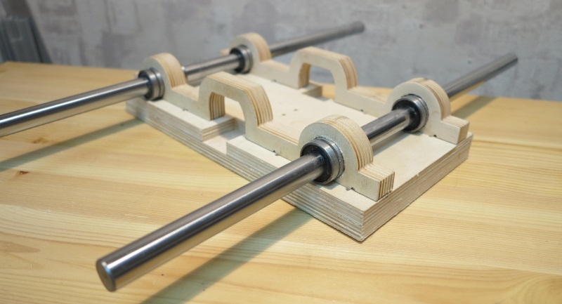
Figure 2 Assembling the table of a desktop CNC milling machine
3.3 The linear bearing holders are driven into the grooves of the sliding table part. The thorn-and-groove connection provides excellent rigidity of the knot, all parts of this knot are made of 18mm plywood. Additionally, by tightening the parts with a bolted connection, we will ensure a long and reliable service life, for this, through the existing hole in the plate, which serves as a guide for the drill, we drill a hole in the end face of the linear bearing holder, as shown in Figure 3, a drill with a diameter of 4mm.

Figure 3 Drilling mounting holes.
3.4 We impose the table itself and, through the existing holes, we fasten it with the help of M4x55 screws from the kit, Figure 4 and 5.

Figure 4 Mounting the slide table bearings.

Figure 5 Mounting the slide table bearings.
3.5 Press the thrust bearings into the details of the table frame. Insert the lead screw with lead nut made of graphite-filled caprolon into the thrust bearings and linear guides into the grooves of the frame elements, Figure 6.

Figure 6. Assembly of the sliding table.
Fasten the frame elements with screws from the kit. For fastening from the sides, use screws 3x25mm, Figure 7. Before screwing in the screws, be sure to drill with a 2mm drill to avoid delamination of the plywood.
If the lead screw is not clamped by the parts of the base of the movable table and there is play of the screw along the axis in the support bearings, use a washer with a diameter of 8 mm, Figure 6.
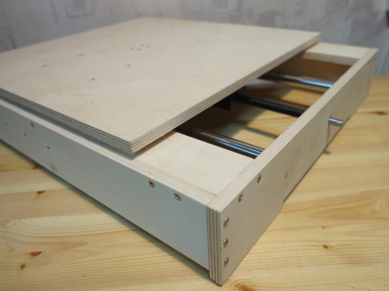
Figure 7. Assembly of the frame of the desktop machine.
3.6 Center the drive nut between the linear bearings and make holes for the screws with a 2mm drill, Figure 8, then use the 3x20 screws from the kit to secure the drive nut. When drilling, be sure to use a stop under the spindle nut so as not to bend the spindle. .

Figure 8. Fastening the running nut.
4 Assembling the portal of the machine.
For assembly you will need:
1) a set of milled parts for assembling the sliding table
2) steel linear guides with a diameter of 16mm (2pcs)
3) linear bearing LM16UU(4pcs)
4) lead screws for the milling machine Modelist2030 - M12 (pitch 1.75mm) with end machining under d=8mm and d=5mm.
For milling machine Modelist3030 - TR12x3 trapezoidal screws (pitch 3mm) with end machining under d=8mm.
5. radial bearings for fastening the lead screws - (2 pcs.)
6. running nut made of graphite-filled caprolon - (- 1 pc.)
4.1 Fasten the sidewall of the portal, Figure 9.

Figure 9. Machine portal assembly.
4.2 Insert the lead screw with nut into the frame of the Z-axis carriage, figure 10.
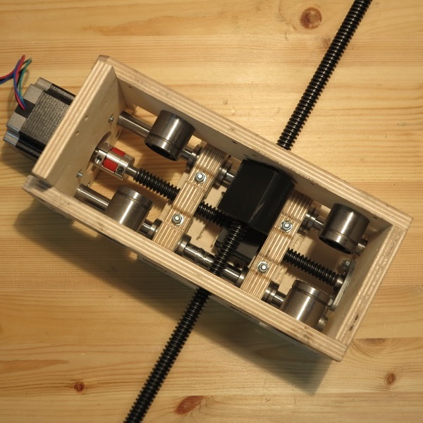
Figure 10 Lead screw installation.
4.3 Insert linear guides, figure 11.

Figure 19 Fastening the lead screw "in the thrust".
4.4 Fasten the second side of the portal, Figure 11.
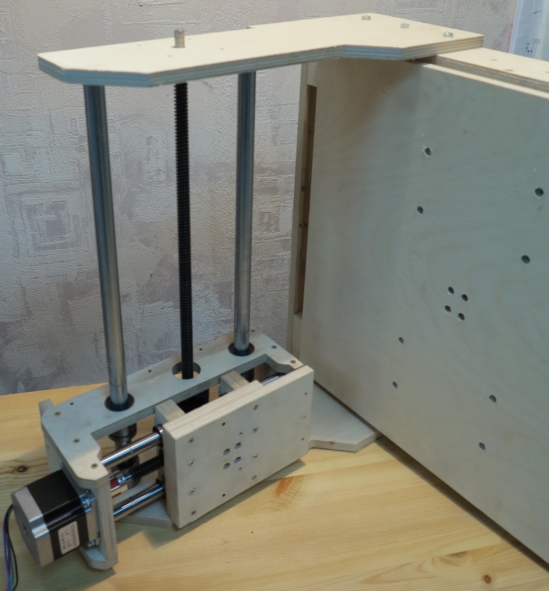
Figure 11. Installing the second side of the portal
If the lead screw is not clamped by the parts of the base of the movable table and there is play along the axis, use a washer with a diameter of 8mm.
4.5 Install and secure the rear wall of the carriage Z, Figure 12.

Figure 12. Fastening the rear wall of the Z carriage.
4.6 Fasten the caprolon running nut with 3x20 screws from the kit, Figure 13.

Figure 13. Attaching the X Axis Lead Nut.
4.7 Fasten the rear wall of the portal, Figure 14, using 3x25 screws from the kit. 
Figure 14. Fastening the rear wall of the portal.
5 Installation of stepper motors.
To install stepper motors, use the fasteners from the set of milled parts of the CNC machine to assemble the Nema23 stepper motor supports for the Modelist3030 milling machine.
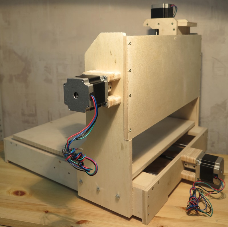
Figure 15. Installation of stepper motors.
Install 5x8mm couplings to connect the motor shaft to the lead screw. Fasten the stepper motors to the machine, for fastening use the M4x55 screw from the kit, Figure 15.
6 Attach the controller to the back of the router, and connect the motor terminals to it.
7 Installing the router.
The router is fastened by the neck of the tool or the body. The standard diameter of the neck of household routers is 43mm. Spindle diameter 300W - 52mm, mounted on the body. For installation, assemble the router mount, fastening details in Figure 16. Use the 3x30mm screw from the kit.
Figure 16 Spindle mount 43mm
Figure 17 CNC Mounted Spindle
When installing Dremel similar tools (engravers), in addition, you will need to additionally fasten the engraver body to the Z carriage with a clamp, Figure 18.

Figure 18 Mounting the engraver on the milling machine.
It is possible to install a nozzle for connecting a vacuum cleaner
For many projects, a CNC router is essential for good and fast results. After some research on the current CNC machines, I came to the conclusion that all machines under 150k cannot meet my needs in terms of space and precision.

What I want:
- working space 900 x 400 x 120 mm
- relatively quiet spindle with high power at low speeds
- highest possible rigidity (for milling aluminum parts)
- highest possible accuracy
- USB interface
- spend up to 150 thousand rubles
With these requirements, I started 3D designing with schematics and drawings, testing the many parts available. The main requirement: the parts must be combined with each other. In the end I decided to build the machine on a 30-B type nut with 8 aluminum frames with 16mm ball bearing spindles, 15mm ball bearing guides and 3 amp NEMA23 stepper motors that fit easily into a pre-built mounting system.
These parts fit together perfectly without the need for special parts.
Step 1: Building the Frame


The key is good planning...
Parts arrived a week after ordering. And in a few minutes, the X-axis was ready. - Easier than I thought! 15mm HRC linear bearings have a very good quality, and after installing them, you immediately understand that they will work very well.
After 2 hours, when assembling a CNC machine on Arduino with my own hands, the first problem appeared: the spindles do not want to get into roller bearings. My freezer isn't big enough for 1060mm spindles, so I decided to get some dry ice, which meant putting the project on hold for a week.
Step 2: Spindle setup


A friend came in with a bag of dry ice, and after a few minutes of freezing, the spindles fit perfectly into the roller bearings. A few more screws and it looks a bit like a CNC machine.
Step 3: Electrical Parts


The mechanical part is finished and I'm moving on to the electrical parts.
Since I am very familiar with Arduino and want to have full control over USB, I first chose an Arduino Uno with a GRBL shield and TB8825 steppers. This configuration works very simply and after a little tweaking the machine is PC manageable. Fine!
But since the TB8825 runs at max 1.9A and 36V (gets very hot), it's enough to start the car, but I noticed a step loss due to too little power. A long milling process at this temperature is a nightmare.
I bought a cheap TB6560 from China (300 rubles each, 3 weeks delivery) and connected them to the GRBL shield. The voltage ratings are not very accurate for this board, you will find ratings from 12V to 32V. Since I already have a 36V power supply, I tried to adapt it.
Result: Two stepper drives work fine, one cannot handle the higher voltage and the other only turns in one direction (cannot change direction).
So, again in search of a good driver ...
TB6600 is my final decision. It is completely covered with an aluminum cooling cover and is easy to set up. Now my steppers work on the X and Y axes with 2.2A and on the Z axis with 2.7A. I could go up to 3A, but since I have a closed box to protect the circuits from aluminum dust, I decided to use 2.2A, which is enough for my needs and generates almost no heat. Also, I don't want the steppers to destroy the car if they make a mistake when I give them too much power.
I thought for a long time about a solution to protect the stepper power supply and frequency converter from small aluminum parts. There are many solutions where the transducer is mounted very high or at a sufficient distance from the milling machine. The main problem is that these devices generate a lot of heat and need active cooling. My final decision is my girlfriend's beautiful pantyhose. I cut them into 30 cm pieces and used them as a protective hose, which is very simple and provides good airflow.
Step 4: Spindle


Choosing the right spindle requires a lot of research. At first I thought about using a stock Kress1050 spindle, but since it only has 1050 watts at 21000 rpm, I can't expect much power at lower speeds.
For my requirements for dry milling aluminum and possibly some steel parts, I need 6000-12000 RPM power.
That's why I finally chose a 3kW variable frequency drive from China (together with a converter) for 25 thousand rubles.
The quality of the spindle is very good. It is quite powerful and easy to set up. I underestimated the weight at 9kg, but fortunately my frame is strong enough and there is no problem with a heavy spindle. (High weight is the reason for the 2.7A Z-axis drive)
Step 5: Job Completed

Ready. The machine works very well, I had a few problems with the stepper drivers, but overall I'm really happy with the result. I spent about 120 thousand rubles and I have a car that exactly suits my needs.
The first milling project was negative form in POM (Parallax occlusion mapping). The machine did a great job!
Step 6: Finishing for aluminum milling


Already in POM, I saw that the torque on the Y-bearing is a little high and the machine bends with high forces around the Y axis. That's why I decided to buy a second rail and upgrade the portal accordingly.
After that, there is almost no backlash due to the force on the spindle. An excellent upgrade and, of course, worth the money (10 thousand rubles).
Now I'm ready for aluminum. With AlMg4.5Mn I got very good results without any cooling.
Step 7: Conclusion
Building your own CNC machine is not really rocket science. I have relatively bad conditions work and equipment, but having a good work plan all you need is a few bits, a screwdriver, clamps and a regular drilling machine. One month in CAD and purchase plan, and four months of assembly to complete installation. The creation of the second machine would have gone much faster, but without any prior knowledge in this area, I had to learn a lot about mechanics and electronics during this time.
Step 8: Details
Here you can find all the main parts of the machine. I would recommend AlMg4.5Mn alloys for all aluminum plates.
Electrical:
I bought all electrical parts on ebay.
- Arduino + GRBL-Shield: ~ 1500 rub.
- Stepper driver: 1000 rub.\pcs
- Power supply: 3000 rubles.
- Stepper motors: ~ 1500 rubles \ pcs
- Milling spindle + inverter: 25 thousand rubles.
Mechanical:
- Linear bearings: link
- Linear rails: link
- Ball circulation spindles: link
- 2x1052mm
- 1x600mm
- 1x250mm
- Fixed spindle bearings + stepper holder: link
- Floating bearing: link
- Spindle-step connections: I ordered Chinese couplings for 180 rubles / piece
- Bottom profiles: link
- X-profiles for rails: link
- Y-profiles for installing X-axis stepper/spindle: link
Portal:
- Profile on linear bearing X: link
- Rear panel / Mounting plate: 5 mm aluminum plate 600×200.
- Y-profiles: 2x link
- Z-profile: link
- Z-mounting plate: 5mm 250×160 Aluminum plate
- Z-sliding plate for spindle mounting: 5mm 200×160 Aluminum plate
Step 9: Software
After using CAD, then CAM and finally G-Code Sender I am very disappointed. After a long search for good software, I settled on Estlcam, which is very convenient, powerful and very affordable (3 thousand rubles).
It completely overwrites the Arduino and controls stepper motors on its own. There are many good documented features. The trial version provides the full functionality of the software, just adding a wait time.
For example, edge search. You just need to connect the wire to the Arduino A5 pin and to the workpiece (if not metal, then use aluminum foil to cover it temporarily). With machine control, you can now press the milling tool against the work surface. As soon as the circuit closes, the machine stops and sets the axle to zero. Very helpful! (usually grounding is not required because the spindle must be grounded)
Step 10: Improve

Until now, the Y and Z axes had temporary plastic brackets to transmit the forces of the spindle nuts and moved the milling spindle accordingly.
The plastic braces were hard plastic, but I don't trust them too much. Imagine that the Z-axis bracket will brake, the milling spindle will simply fall (obviously in the process of milling).
That is why I have now made these brackets from aluminum alloy (AlMgSi). The result is attached in the picture. They are now much stronger than the plastic version I made before without a router.
Step 11: Machine in operation


Now, with a little CNC practice, a do-it-yourself woodworking machine already gives very good results (for a hobby). These pictures show an AlMg4.5Mn nozzle. I had to mill it from both sides. In the last photo, what happened without polishing or sandpaper.
I used a 6mm VHM cutter with 3 blades. I found that 4-6mm tools give very good results on this machine.
Difficult to manufacture, in addition to the technical components, it has an electronic device, which can only be installed by a specialist. Contrary to this opinion, the ability to assemble a CNC machine with your own hands is great if you prepare the necessary drawings, diagrams and component materials in advance.
Carrying out preparatory work
When designing a CNC with your own hands at home, you need to decide according to which scheme it will work.
Often, a used one is taken as the basis of a future apparatus.
The drilling machine can be used as the basis for a CNC machine
It will require the replacement of the working head with a milling head.
The greatest difficulty in designing a CNC machine with your own hands is the creation of a device with which the working tool moves in three planes.
Partially solve the problem will help carriages taken from a conventional printer. The tool will be able to move in both planes. It is better to choose carriages for a CNC machine from a printer that has large dimensions.
Such a scheme allows you to later connect to the machine control. The downside is that the CNC milling machine only works with wood, plastic products, products made of thin metal. This is due to the fact that the printer carriages do not have the necessary rigidity.
Attention must be paid to the engine of the future unit. Its role is reduced to the movement of the working tool. The quality of work and the possibility of performing milling operations depend on this.
A good option for a homemade CNC router is a stepper motor.

An alternative to such an engine is an electric motor, previously improved and adjusted to the standards of the device.
Anyone using a stepper motor allows you to not use a screw drive, this does not affect the capabilities of such a wood CNC in any way. It is recommended to use toothed belts for milling on such a unit. Unlike standard belts, they do not slip on pulleys.
It is required to correctly design the milling cutter of the future machine, for this you will need detailed drawings.
Materials and tools required for assembly
The general set of materials for a CNC machine includes:
- cable 14–19 m long;
- processing wood;
- cutter chuck;
- a frequency converter having the same power as the spindle;
- bearings;
- control board;
- water pump;
- cooling hose;
- three stepping motors for three axes of movement of the structure;
- bolts;
- protective cable;
- screws;
- plywood, chipboard, wood board or metal structure to choose as the body of the future device;
- soft clutch.

It is recommended that when making your own hands, use a spindle with coolant. This will allow you not to turn it off every 10 minutes to cool down. A home-made CNC machine is suitable for work, its power is at least 1.2 kW. The best option will be a device with a power of 2 kW.
The set of tools required for the manufacture of the unit includes:
- hammers;
- electrical tape;
- assembly keys;
- glue;
- screwdriver
- soldering iron, sealant;
- grinder, it is often replaced with a hacksaw;
- pliers, welding machine, scissors, pliers.
A simple CNC do-it-yourself machine
Procedure for assembling the machine
Homemade CNC milling machine is assembled according to the scheme:
- production of drawings and diagrams of the device indicating the electrical system;
- purchase of materials containing a future home-made CNC machine;
- installation of a bed, engines, a working surface, a portal, a spindle will be mounted on it;
- portal installation;
- setting the Z axis;
- fixing the working surface;
- spindle installation;
- installation of a water-cooling system;
- installation of the electrical system;
- connection of the board, with its help the device is controlled;
- software setup;
- start-up of the unit.
The basis for the bed is a material made of aluminum.

The frame must be made from aluminum
Profiles of this metal are selected with a section of 41 * 81 mm with a plate thickness of 11 mm. The body of the bed itself is connected using aluminum corners.
The installation of the portal will determine how thick the product can be processed by the CNC machine. Especially if it's handmade. The higher the portal, the thicker the product it can process. It is important not to install it too high, as this design will be less durable and reliable. The portal moves along the X axis and carries the spindle on itself.
An aluminum profile is used as a material for the working surface of the unit. Often take a profile with T-slots. For home use accept, its thickness is at least 17 mm.
After the frame of the device is ready, proceed to install the spindle. It is important to install it vertically, since in the future it will need to be adjusted, this is done to fix the required angle.
To install the electrical system, the presence of the following components is required:
- power unit;
- computer;
- stepper motor;
- pay;
- stop button;
- motor drivers.

The system requires an LPT port. In addition, it is installed that controls the operation of the apparatus and allows you to answer the question of how to perform this or that operation. The control is connected via motors to the milling machine itself.
After the electronics is installed on the machine, you will need to download the drivers and programs necessary for operation.
Common Build Mistakes
A common mistake when assembling a CNC machine is the lack of a drawing, but the assembly is carried out according to it. As a result, there are omissions in the design and installation of apparatus structures.
Often the incorrect operation of the machine is associated with incorrectly selected frequency converter and spindle.

For the correct operation of the machine, it is necessary to choose the right spindle
In many cases, stepper motors do not receive proper power, so a special separate power supply must be selected for them.
It must be taken into account that a properly installed wiring diagram and software allows you to perform numerous operations of various levels of complexity on the device. Do-it-yourself CNC machine can be done by a middle-level master, the design of the unit has a number of features, but it is not difficult to assemble the parts with the help of drawings.
It is easy to work with a CNC, compiled with your own hands, you need to study the informative base, conduct a series of training work and analyze the condition of the unit and parts. Do not rush, pull moving parts or open the CNC.
The condition for the performance of professional woodwork is the presence. Commercially available roads and not everyone can afford it. Therefore, many make them with their own hands, saving money and enjoying the creative process.
There are two options for the manufacture of mini machines for:
- purchase of a set of parts and its manufacture (Modelist kits costing from 40 to 110 thousand rubles);
- make it with your own hands.
Consider the manufacture of mini CNC milling machines with your own hands.
Choice of design features
The list of actions in the development, manufacture of a mini device for wood milling is as follows:
- Initially, you need to decide what kind of work we are talking about. This will tell you what dimensions and thicknesses of parts can be processed on it.
- Make a layout and an estimated list of parts for a homemade desktop machine for DIY manufacturing.
- Select software to bring it into working condition so that it works according to a given program.
- Purchase the necessary components, parts, products.
- Having drawings, make the missing elements with your own hands, assemble and debug the finished product.
Design
A homemade machine consists of the following main parts:
- bed with a table placed on it;
- calipers with the ability to move the cutting cutter in three coordinates;
- spindle with cutter;
- guides for moving calipers and portal;
- a power supply unit that provides electricity to the motors, a controller or a switching board using microcircuits;
- drivers to stabilize the work;
- sawdust vacuum cleaner.
Guides are installed on the frame to move the portal along the Y axis. Guides are placed on the portal to move the caliper along the X axis. The spindle with the cutter is mounted on the caliper. It moves along its guides (Z-axis).
The controller and drivers provide automation of the CNC machine by transmitting commands to the electric motors. Using the Kcam software package allows you to use any controller and provides motor control in accordance with the part drawing entered into the program.
The design must be made rigid in order to withstand the working forces that arise during operation and not lead to vibrations. Vibrations will lead to a decrease in the quality of the resulting product, tool breakage. Therefore, the dimensions of the fasteners must ensure the solidity of the structure.
A homemade CNC milling machine is used to obtain a three-dimensional 3D image on wood detail. It is attached to the table of this unit. It can also be used as an engraver. The design ensures the movement of the working body - the spindle with the cutter installed in accordance with the specified program of actions. The movement of the caliper along the X and Y axes occurs along polished guides using stepper motors.
Moving the spindle along the vertical Z axis allows you to change the depth of processing on the created drawing on the tree. To obtain a 3D relief drawing, you need to make drawings. It is advisable to use different kinds cutters that will allow you to get the best image display options.
Selection of components
For guides, steel rods D = 12 mm are used. For better movement of the carriages, they are ground. Their length depends on the size of the table. You can use hardened steel rods from a dot matrix printer.
Stepper motors can be used from there. Their parameters: 24 V, 5 A.
It is desirable to provide fixing of cutters with a collet.
It is better to use a factory-made power supply for a home-made mini milling machine, since performance depends on it.
The controller needs to use capacitors and resistors in SMD packages for surface mounting.
Assembly
To assemble a home-made machine for milling 3D wood parts with your own hands, you need to make drawings, prepare essential tool, accessories, make the missing parts. After that, you can start assembling.
The do-it-yourself assembly sequence of a mini CNC machine with 3D processing consists of:
- caliper guides are installed in the sidewalls together with the carriage (without screws).
- the carriages are moved along the guides until their motion becomes smooth. Thus, the holes in the caliper are lapped.
- tightening bolts on calipers.
- fixing assembly units on the machine and installing screws.
- installation of stepper motors and their connection with screws using couplings.
- the controller is allocated in a separate block to reduce the influence of operating mechanisms on it.
A homemade CNC machine after assembly must be tested! Testing 3D processing is carried out by using sparing modes to identify all problems and fix them.
Work in automatic mode is provided software. Advanced computer users can use power supplies and drivers for controllers, stepper motors. The power supply converts the incoming alternating current (220 V, 50 Hz) into direct current necessary to power the controller and stepper motors. For them, machine control from a personal computer passes through the LPT port. Working programs are Turbo CNC and VRI-CNC. CorelDRAW and ArtCAM graphic editor programs are used to prepare the drawings necessary for implementation in a tree.
Results
Homemade mini CNC milling machine for 3D parts is easy to operate, ensures accuracy and quality of processing. If you need to do more complex work, you need to use stepper motors of greater power (for example: 57BYGH-401A). In this case, to move the calipers, you need to use toothed belts to rotate the screws, and not a clutch.
The installation of the power supply (S-250-24), switching board, drivers can be done in the old case from the computer, modifying it. It can be equipped with a red "stop" button for emergency shutdown of equipment.
You may also be interested in articles:
Do-it-yourself wood slotting machine How to make a wood planer with your own hands Copy-milling machines for wood
The aim of this project is to create a desktop CNC machine. It was possible to buy a ready-made machine, but its price and dimensions did not suit me, and I decided to build a CNC machine with the following requirements:
- usage simple tools(only need a drilling machine, band-saw and hand tools)
- low cost (I was looking for low cost, but I still bought items for about $600, you can save a lot by buying items in the appropriate stores)
- small footprint(30"x25")
- Normal working space (10" X, 14" Y, 4" Z)
- high cutting speed (60" per minute)
- a small number of elements (less than 30 unique)
- available elements (all elements can be bought in one hardware and three online stores)
- the possibility of successful processing of plywood
Other people's machines
Here are some photos of other machines that have been assembled according to this article

Photo 1 - Chris and a friend assembled the machine by cutting parts out of 0.5" acrylic using laser cutting. But everyone who has worked with acrylic knows that laser cutting is good, but acrylic does not tolerate drilling, and there are many holes in this project .they did Good work, more information can be found on Chris's blog. I especially liked making a 3D object with 2D cuts.

Photo 2 - Sam McCaskill made a really nice desktop CNC machine. I was impressed that he did not simplify his work and cut out all the elements by hand. I am impressed with this project.

Photo 3 - Angry Monk's used DMF parts cut with a laser cutter and toothed belt driven motors converted to propeller motors.

Photo 4 - Bret Golab's assembled the machine and set it up to work with Linux CNC (I also tried to do this, but I couldn't because of the difficulty). If you are interested in his settings, you can contact him. He did a great job!
I'm afraid I don't have enough experience and knowledge to explain the basics of CNC, but the CNCZone.com forum has an extensive section on homemade machines, which helped me a lot.

Cutter: Dremel or Dremel Type Tool
Axes options:
X axis
Travel Distance: 14"
Speed: 60"/min
Acceleration: 1"/s2
Resolution: 1/2000"
Pulses per inch: 2001
Y-axis
Travel Distance: 10"
Drive: Toothed belt drive
Speed: 60"/min
Acceleration: 1"/s2
Resolution: 1/2000"
Pulses per inch: 2001
Z-axis (up-down)
Travel Distance: 4"
Drive: Screw
Acceleration: .2"/s2
Speed: 12"/min
Resolution: 1/8000"
Pulses per inch: 8000
Required Tools
I aimed to use popular tools that can be purchased at a regular craft store.

Power tool:
- band saw or jigsaw
- drilling machine (drills 1/4", 5/16", 7/16", 5/8", 7/8", 8mm (about 5/16")), also called Q
- a printer
- Dremel or similar tool (to be installed in the finished machine).
Hand tool:
- rubber hammer (for planting elements in place)
- hexagons (5/64", 1/16")
- screwdriver
- glue stick or spray glue
- Adjustable wrench (or socket wrench with ratchet and 7/16" socket)
Necessary materials
The attached PDF file (CNC-Part-Summary.pdf) provides all costs and information about each item. Only summarized information is provided here.

Sheets---$20
- Piece 48"x48" 1/2" MDF ( any will do sheet material 1/2" thick. I plan to use UHMW in the next version of the machine, but now it is too expensive)
- A piece of 5"x5" 3/4" MDF (this piece is used as a spacer so you can use any 3/4" piece of material)
Motors and controllers --- $255
-A whole article can be written about the choice of controllers and motors. In short, you need a controller capable of controlling three motors and motors with about 100 oz/in torque. I bought motors and a ready-made controller and everything worked well.
Hardware --- $275
-I bought these items in three stores. I got the simple parts from the hardware store, the specialized drivers I got from McMaster Carr (http://www.mcmaster.com), and the bearings, which I need a lot, I bought from an online retailer for $40 for 100 pieces (it's quite a bargain). , many bearings remain for other projects).
Software --- (Free)
-You need a program to draw your design (I use CorelDraw) and now I use trial version Mach3, but I have plans to switch to LinuxCNC (an open source machine controller using Linux)
Head Unit --- (Optional)
-I installed Dremel on my machine, but if you are interested in 3D printing (like RepRap) you can install your device.
Printing templates
I had some experience with a jigsaw, so I decided to glue on the templates. It is necessary to print PDF files with templates placed on the sheet, stick the sheet on the material and cut out the details.

File name and material:
All: CNC-Cut-Summary.pdf
0.5" MDF (35 8.5"x11" template sheets): CNC-0.5MDF-CutLayout-(Rev3).pdf
0.75" MDF: CNC-0.75MDF-CutLayout-(Rev2).pdf
0.75" aluminum tube: CNC-0.75Alum-CutLayout-(Rev3).pdf
0.5"MDF (1 48"x48" pattern sheet): CNC-(One 48x48 Page) 05-MDF-CutPattern.pdf
Note: I am attaching CorelDraw drawings in original format (CNC-CorelDrawFormat-CutPatterns (Rev2) ZIP) for those who would like to change something.
Note: There are two options for MDF 0.5". MDF-CutPattern.pdf) with one 48"x48" sheet for printing on a large format printer.
Step by step:
1. Download three PDF templates.
2. Open each file in Adobe Reader
3. Open the print window
4. (IMPORTANT) Disable Page Scaling.
5. Check that the file has not been scaled by accident. The first time I did not do this, and printed everything at a scale of 90%, as described below.
Gluing and cutting elements
Glue the printed templates on the MDF and on the aluminum pipe. Next, just cut out the part along the contour.


As mentioned above, I accidentally printed the templates at 90% scale, and did not notice this until I started cutting. Unfortunately, I did not understand this until this stage. I was left with 90% scale templates and moving across the country I got access to a full size CNC. I could not resist and cut out the elements with this machine, but I could not drill them with reverse side. That is why all the elements in the photos are without template pieces.

drilling
I didn't count exactly how many, but this project uses a lot of holes. The holes that are drilled on the ends are especially important, but take the time to get them, and you will rarely need to use a rubber hammer.
Places with holes in the lining on top of each other is an attempt to make grooves. Perhaps you have a CNC machine that can do this better.
If you have reached this step, then I congratulate you! Looking at a bunch of elements, it is quite difficult to imagine how to assemble a machine, so I tried to make detailed instructions similar to LEGO instructions. (attached PDF CNC-Assembly-Instructions.pdf). Looks pretty interesting step by step photos assemblies.


Ready!
The machine is ready! I hope you made and run it. I hope that the article does not miss important details and points. Here is a video that shows the machine cutting a pattern on pink foam.