In the arsenal home master there are many tools for all occasions.
The welding machine is an indispensable device for real craftsmen. It can be bought in stores. However, it is much more interesting and cheaper to assemble with your own hands.
Some also have a welding machine, which every craftsman dreams of.
Today it can be purchased in specialized stores. There are many models. Various accessories for the device are sold Consumables. Is it possible to make a welding machine with your own hands? The answer is simple: it is possible and even necessary!
Types of welding machines
All devices for welding work are divided into gas and electric. Gas installations not quite suitable for home use. They require special treatment, as they are equipped with explosive gas cylinders. Therefore, we should only talk about electrical devices. They are also different:

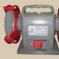
The welding inventory is economical and ideal for home use.
- Generators. These installations have their own current generator. Differ in very big weight and the bulky sizes. Not suitable for home assembly and use.
- Transformers. Such devices can be powered by 220 or 380 volts. They are very popular, especially semi-automatic.
- Inverters. Very economical fixtures, ideal for the home. Differ in small weight, but rather difficult electronic scheme.
- Rectifiers. Easy to make and use. Even novice welders can make quality seams. Ideal for DIY assembly.
How to start assembling an inverter apparatus?
To assemble the inverter, you need to select a circuit that will provide the necessary operating parameters for the device. It is recommended to use Soviet-made parts. This is especially true for diodes, capacitors, transistors, resistors, chokes, thyristors and finished transformers. The equipment assembled on these parts does not require complex adjustment. All parts are very compactly located on the board. For the manufacture of the device with your own hands, you can select the following options:
- The welding machine must work with electrodes up to 4-5 mm in diameter.
- The value of the operating current is not more than 250 A.
- Power source - household network voltage 220 V.
- Welding current adjustment within 30-220 A.
The welding machine consists of several blocks: a power supply, a rectifier and an inverter.
You can start making an inverter-type welding machine with your own hands by winding the transformer in this order:

To assemble the inventory, you will need a ferrite core.
- You need to take a ferrite core Ш8х8. You can use W7x7.
- Primary winding No. 1 consists of 100 turns wound with wire of the PEV 0.3 brand.
- Secondary winding No. 2 is wound with a wire with a cross section of 1 mm. The number of turns is 15.
- Winding No. 3 - 15 turns of PEV wire 0.2 mm.
- Windings No. 4 and No. 5 consist of 20 turns of wire with a cross section of 0.35 mm.
- To cool the transformer, you can use a 220 V, 0.13 A fan. These parameters correspond to a fan from a Pentium 4 computer.
In order for the transistor switches to work smoothly, they need to be energized after the rectifier and smoothing capacitors. The rectifier unit is assembled according to a simple scheme on the board. All nodes of the welding machine are fixed in the body. Well, if the master’s household has a suitable case from a radio device, then you won’t have to make it from improvised materials.

On the front side housings place an LED indicator, which, by its glow, notifies you that the device is connected to the network. Here you can install an additional switch of any type and a protective fuse. The fuse can be installed on the rear wall, as well as in the case itself. It depends on its design and dimensions. Variable resistance, with which the operating current will be adjusted, is also located on the front side of the case.
If the electrical circuits are assembled correctly, everything is checked with a tester or other device, you can test the device.
Back to indexHow to assemble a transformer device?
The process of assembling a transformer welding apparatus is somewhat different from the previous version. It works on alternating current. For DC welding, a simple attachment is assembled to it. To assemble the device with your own hands, you need to get transformer iron for the core and several tens of meters of a thick copper bus or just a thick wire. You can look for these things at the collection points of non-ferrous and ferrous metal, with friends and acquaintances. It is recommended to make the core U-shaped, but it is also possible to make it round, toroidal. Some craftsmen successfully use the stator of a burned-out electric motor as a core. For a U-shaped core, the assembly order can be as follows:

To perform the primary winding, a winding wire is required.
- Dial the core of transformer iron to its optimal cross section of about 55 square centimeters. You can do more, but the device will be heavy. With a cross section of less than 30 cm², the device may lose some of its qualities.
- For the primary winding, a special winding wire with a cross section of 5-7 mm² is ideal. It is made of copper, has heat-resistant fiberglass or cotton insulation. This is very important, since during operation the winding can heat up to temperatures above 100 degrees. The cross section of the wire is usually square or rectangular. It is not always possible to find such a wire. You can replace it with an ordinary wire of the same cross section and modify it: remove the insulation, wrap the wire with strips of fiberglass, soak it thoroughly with a special electrical varnish and dry it. The primary winding consists of 200-230 turns.
- For the secondary winding, you can first wind 50-60 turns. You don't need to cut the wire. It is necessary to turn on the primary winding in the network. Find a place on the wires of the secondary winding where the voltage will be equal to 60-65 V. In order to find this point, you have to unwind or wind additional turns. You can wind aluminum wire, increasing the cross section by 1.7 times.
- The simplest transformer is assembled. It remains to place it in a suitable case.
- For the conclusions of the secondary winding, terminals are made of copper. A tube with a diameter of about 10 mm and a length of 3-4 cm is taken. Its end is riveted, and a hole is drilled in it, the diameter of which is 10 mm. Insert the end of the wire, cleaned of insulation, into the other end of the tube and crimp it with light blows of the same hammer. To enhance the contact of the wire with the tube-terminal, notches can be applied to it with a core. Homemade terminals are screwed to the body with M10 bolts and nuts. It is advisable to select copper parts. It is possible, when winding the secondary winding, to make taps every 5-10 turns of wire. These taps will allow you to change the voltage on the electrode in steps.
- It remains to make an electrode holder. It can be made from a pipe with a diameter of about 18-20 mm. Its total length is about 25 cm. At the ends, 3-4 cm from the end, notches are cut to about half the diameter. The electrode is inserted into the recess and pressed against the spring from the welded piece steel wire 6 mm in diameter. The same wire from which the secondary winding is made is fastened to the other end with a screw and an M8 nut. A rubber tube of suitable inner diameter is put on the holder. It is recommended to connect the device to the home network using a switch and wires with a cross section of 1.5 mm² or more. The current in the primary winding usually does not exceed 25 A. In the secondary winding, it can be from 60 to 120 A. During operation, it is recommended to take a break after 10-15 electrodes with a diameter of 3 mm so that the transformer cools down. With thinner electrodes, this can be omitted. In cutting mode, breaks should be taken more often.
Your own welding machine will always come in handy on the farm, albeit infrequently, but it is very necessary, and sometimes it’s just not possible without it. Especially if you are used to making things yourself. Therefore, do-it-yourself microwelding, made from improvised materials and outdated household appliances- just what we need.
We will not consider the option of buying a factory welding machine, as this will require money, but we will immediately follow the path of making home-made mini welding at home. There are several quite affordable schemes of welding machines for self-production, but the contact or spot welding machine seems to be the simplest and least expensive.
So that there is no doubt right away why we will describe exactly the option as, for this we will clearly determine that for this we will not need theoretical knowledge of the electrical engineering course and virtuoso mastery of locksmith skills. Everything will be simple, clear and accessible.
Training
The main part of all electric welding machines is a power transformer (if you do not consider modern electronic welding equipment, also called inverters). Therefore, first of all, we will need to take it from somewhere and the most suitable and affordable option for this there will be an old broken microwave oven. And the bigger it is, the better for us. More precisely, the more powerful its transformer will be and the stronger our welding.
If you want to find an old microwave oven, it’s not a problem by looking for it either from your closest friends (those who are richer), or by looking at free classifieds boards, where they are often offered for a nominal fee. From the insides microwave oven we will be interested in only one detail - this is a high-voltage transformer.
Here we will immediately determine, without going into particular technical calculations, that contact welding made from such a transformer from a microwave oven will be able to generate a welding current from 800 to 1000 amperes. This current is quite enough to weld together strips of metal up to 2 mm thick, even from stainless steel, which is a difficult task for simple welding.
Preparation of the welding transformer
The high-voltage microwave transformer is a steel core, recruited from thin steel plates and located inside its two windings of copper wire. We need the winding that looks smaller, it is considered primary and will be wound from a thicker conductor. The other winding (the one that is larger in size) will be secondary and we simply do not need it. Here it is in the first place and must be dismantled from the transformer.
To do this, you need to disassemble the transformer, or rather, its core, which is made of steel plates, tightly compressed and fastened together by two thin welds. Here we need to cut these welds, for which you can use either a hacksaw or a grinder with a thin circle.
Keep in mind! There may be transformers fastened with an outer tin casing and bolts. In this case, simply unscrew the bolted connections and carefully open the casing. Everything, problems with further disassembly should not arise.
Perform this operation of disassembling the transformer very carefully, since we still need the primary winding, so in no case do we bend or scratch it when removing it. But we don’t stand on ceremony with the secondary winding, it can be cut and pulled out with a hammer and a chisel in parts, it will be much easier.
As a result, we have a whole and undamaged primary winding of the transformer and its steel core in the form of two separated parts.
Next, we wind the secondary winding of our future welding transformer. Here we still have to buy a piece of new copper wire in insulation with a cross section of 50 mm2 or about 8 mm in diameter. To do this, we take it and wind it around the central E-shaped magnetic circuit of the core, making two full turns. We will need all such copper wire, taking into account the output to the welding contacts of about 50 cm, the only condition is that the winding must be made so that it is the middle of the conductor.
Then we assemble the transformer, while the primary winding should remain in its place, and our new winding made of copper wire should be placed instead of the secondary. We fasten the two parts of the core using the usual two-component epoxy resin and clamp the entire structure in a locksmith vice for a day. After the epoxy has dried, the transformer is completely ready for operation. Photo
Construction assembly
Having made test measurements with a simple tester, when connecting the primary winding to a 220 V network, we have a voltage of about 2 V on the secondary winding, but with an electric current of about 800 A (this is not measured, but calculated - here we take our word for it). This current strength is more than enough to make a strong welded joint of two metal plates.
Now we make the body. To do this, you can use any materials at hand, such as wood, plywood, sheets of durable plastic or galvanized sheet. The main thing is to place the transformer itself and the lower contact on a solid foundation, since one of the conditions is a strong contact of the welding electrodes with the surface to be welded, which, in turn, is possible with the application of great efforts.
It remains to make welding contacts and the mechanical part of our welding machine will be completed. One of the contacts will be at the bottom and it will be fixed, so it is better to make its base from a wooden block 30 cm long, so it will be easier to attach it to the base. At the end of the bar, using the manufactured bracket, we fasten the welding electrode, to which we connect one of the wires of the power winding of the transformer.
Welding electrodes for microwelding can be made with your own hands from a copper bar with a cross section of 5 to 10 mm in diameter, making a slight sharpening at the end at the point of contact with the surface to be welded. It is better, of course, to use tungsten rods or special electrodes for resistance welding from an alloy of beryllium bronze with zirconium additives for this.
We make the upper contact in the form of a lever. To do this, you can also use a wooden block or a not very massive metal profile in the form of a pipe of small diameter. The only thing is that on a metal lever, the design of the welding electrode attachment will be more difficult, since it will also need to be isolated. At the base of the moving contact lever, we must provide a spring so that the lever in the normal state is constantly in the upper position. To do this, you can use a steel spring or an elastic rubber band.
In conclusion, we complete the electrical circuit of the mini welder by connecting a wire with a standard plug for a 220 V network to the ends of the primary winding of our power transformer, and it is imperative to provide a 220 V switch. For this, both the old wire from the microwave oven and any switch designed for a voltage of 220 V and a current of 5 A, it is better if it is a push-type microswitch (mic).
Important! Do not forget to isolate all electrical connections and contacts well.
Everything, your own hand-made mini welder for a summer residence or at home is ready and, as it turned out, making it yourself is not so difficult. Now you can safely weld small flat parts from various metals, but for this you will need to practice and gain practical skills.
And also you can watch the video on how to make contact spot welding with your own hands and how you can use it.

20 years ago, at the request of a friend, he assembled a reliable welder to work from a 220 volt network. Before that, he had problems with his neighbors due to a voltage drop: he needed an economical mode with current control.
After studying the topic in reference books and discussing the issue with colleagues, I prepared an electrical thyristor control circuit and mounted it.
This article is based on personal experience I tell you how I assembled and set up a DC welding machine with my own hands based on a home-made toroidal transformer. It turned out in the form of a small instruction.
I still have the scheme and working sketches, but I can’t give photographs: there were no digital devices then, and my friend moved.
Versatile Capabilities and Tasks
A friend needed an apparatus for welding and cutting pipes, angles, sheets of different thicknesses with the ability to work with electrodes 3 ÷ 5 mm. About welding inverters at that time did not know.
We settled on the design of direct current, as a more universal one, providing high-quality seams.
The negative half-wave was removed with thyristors, creating a pulsating current, but they did not begin to smooth out the peaks to an ideal state.

The welding output current control circuit allows you to adjust its value from small values for welding up to 160-200 amperes, which are necessary when cutting with electrodes. She:
- made on a board of thick getinaks;
- closed with a dielectric casing;
- mounted on the housing with the output of the adjusting potentiometer handle.
The weight and dimensions of the welding machine turned out to be smaller compared to the factory model. They placed it on a small cart with wheels. To change jobs, one person freely rolled it without much effort.
The power wire through an extension cord was connected to the connector of the introductory electrical panel, and the welding hoses were simply wound around the body.
Simple structure of DC welding machine
According to the principle of installation, the following parts can be distinguished:
- homemade transformer for welding;
- its power supply circuit from the network 220;
- output welding hoses;
- power unit of the thyristor current regulator with an electronic control circuit from the pulse winding.

The pulse winding III is located in the power zone II and is connected through the capacitor C. The amplitude and duration of the pulses depend on the ratio of the number of turns in the capacitance.
How to make the most convenient transformer for welding: practical tips
Theoretically, any model of transformer can be used to power the welding machine. The main requirements for it:
- provide arc ignition voltage at idle;
- reliably withstand the load current during welding without overheating of the insulation from prolonged operation;
- meet the requirements of electrical safety.
In practice, I have met different designs homemade or factory transformers. However, they all require an electrical calculation.
I have been using a simplified technique for a long time, which allows you to create fairly reliable designs for a medium-precision transformer. This is quite enough for domestic purposes and power supplies for amateur radio devices.
It is described on my website in the article This is an average technology. It does not require specification of grades and characteristics of electrical steel. We usually do not know them and cannot take them into account.
Features of the manufacture of the core
Craftsmen make magnetic wires from electrical steel of various profiles: rectangular, toroidal, double rectangular. They even wind coils of wire around the stators of burned out powerful asynchronous electric motors.
We had the opportunity to use decommissioned high-voltage equipment with dismantled current and voltage transformers. They took strips of electrical steel from them, made two rings out of them - donuts. The cross-sectional area of each was calculated to be 47.3 cm 2 .
They were isolated with varnished cloth, fastened with a cotton ribbon, forming the figure of a lying eight.

A wire was wound on top of the reinforced insulating layer.
Secrets of the power winding device
The wire for any circuit must be with good, durable insulation, designed for long-term operation when heated. Otherwise, during welding, it will simply burn out. We proceeded from what was at hand.
We got a wire with varnish insulation, covered with a fabric sheath on top. Its diameter - 1.71 mm is small, but the metal is copper.
Since there was simply no other wire, they began to make the power winding out of it with two parallel lines: W1 and W’1 with the same number of turns - 210.
The core bagels were mounted tightly: so they have smaller dimensions and weight. However, the flow area for the winding wire is also limited. Installation is difficult. Therefore, each half-winding of the power supply was smashed into its rings of the magnetic circuit.
In this way we:
- doubled the cross section of the power winding wire;
- saved space inside the bagels to accommodate the power winding.
Wire Alignment
You can get a tight winding only from a well-aligned core. When we removed the wire from the old transformer, it turned out to be twisted.
Figured out the required length. Of course, it wasn't enough. Each winding had to be made from two parts and spliced with a screw clamp right on the donut.
The wire was stretched on the street along its entire length. They took the pliers in hand. They clamped opposite ends with them and pulled with force in different directions. The vein turned out to be well aligned. They twisted it into a ring with a diameter of about a meter.
Technology of winding wire on a torus
For the power winding, we used the rim or wheel winding method, when a large-diameter ring is made from the wire and wound inside the torus by rotating one turn at a time.
The same principle is used when putting on a winding ring, for example, on a key or key chain. After the wheel is brought inside the donut, they begin to gradually unwind it, laying and fixing the wire.
Alexey Molodetsky showed this process well in his video "Winding a torus on a rim".
This work is difficult, painstaking, requires perseverance and attention. The wire must be tightly laid, counted, control the process of filling the internal cavity, keep a record of the wound number of turns.
How to wind a power winding
For her, we found a copper wire of a suitable section - 21 mm 2. Figured out the length. It affects the number of turns, and the open-circuit voltage necessary for a good ignition of the electric arc depends on them.
We made 48 turns with an average output. In total, there were three ends on a donut:
- medium - for direct connection"plus" to the welding electrode;
- extreme - to thyristors and after them to ground.
Since the donuts are fastened and the power windings are already mounted on them along the edges of the rings, the winding of the power circuit was performed using the “shuttle” method. The aligned wire was folded into a snake and pushed for each turn through the holes of the donuts.
The tapping of the middle point was performed by a screw connection with its insulation with varnished cloth.
Reliable welding current control circuit
Three blocks are involved in the work:
- stabilized voltage;
- formation of high-frequency pulses;
- separation of pulses on the circuit of control electrodes of thyristors.
Voltage stabilization
An additional transformer with an output voltage of about 30 V is connected from the power winding of the 220 volt transformer. It is rectified by a diode bridge based on D226D and stabilized by two D814V zener diodes.
In principle, any power supply with similar electrical characteristics output current and voltage.

Impulse block
The stabilized voltage is smoothed by capacitor C1 and fed to the pulse transformer through two bipolar transistors of direct and reverse polarity KT315 and KT203A.


Transistors generate pulses on the primary winding Tr2. This is a toroidal type pulse transformer. It is made on permalloy, although a ferrite ring can also be used.
The winding of three windings was carried out simultaneously with three pieces of wire with a diameter of 0.2 mm. Made in 50 turns. The polarity of their inclusion matters. It is shown as dots in the diagram. The voltage on each output circuit is about 4 volts.
Windings II and III are included in the control circuit of power thyristors VS1, VS2. Their current is limited by resistors R7 and R8, and part of the harmonic is cut off by diodes VD7, VD8. Appearance We checked the pulses with an oscilloscope.
In this chain, the resistors must be selected for the voltage of the pulse generator so that its current reliably controls the operation of each thyristor.
The trigger current is 200 mA and the trigger voltage is 3.5 volts.

Do-it-yourself welding machines for the home are most often created by craftsmen from improvised materials.
If you do not have the opportunity or desire to buy a welding machine, then you can assemble it yourself using ready-made elements.
However, to speed up the assembly process, ready-made assemblies and parts can be used. The electrode holder can also be made on your own from the materials available in the arsenal of the home master.
The simplest welding machine

In the household of a home master, a step-down transformer S-B22, IV-10, IV-8 can be found, the power of which is 1-2 kW. It lowers the voltage from 220 V to 36 V, serves to power the power tool.
Welding machines based on such transformers can be assembled even with a failed winding.
The welding machine is manufactured as follows:
![]()
Remove the secondary winding from the transformer.
- secondary windings are removed from the coils without damaging the primary ones;
- the middle primary coil is rewound with the same wire, creating taps with a total of 8-10 pieces after 30 turns. (for convenience, it is better to number each of them as they are created);
- two extreme coils are filled with a multi-core cable (three 6-8 mm wires with a thin phase, 12-13 m is spent on each coil);
- a copper pipe with a diameter of 10-12 mm is used for a terminal for a VO cable (one side compresses the wires, the second is flattened, drilled for fasteners with a diameter of 10 mm);
- on the top panel of the transformer, the M6 fasteners are replaced by more powerful ones (M10), VO terminals are attached to them;
- A board with 10 holes for software is made from textolite, M6 fasteners are inserted into each hole.
Welding machines of this design are powered by a 380/220 V network. In the first case, the software of the extreme, then the middle coils are connected in series. In the second variant, the extreme windings are connected in parallel, the middle winding is connected in series to the same circuit. VO taps are put into the terminals of the textolite plate 1 - 10. The current is regulated by terminals 1 - 10.
It is not recommended to perform large volumes of work with this SA (maximum 15 “troika” electrodes).
For cutting metal, the second end of the cable leading to the holder is connected to the cutting terminal (on the side of the middle coil of the software). The current characteristics of the VO correspond to 60-120 A, in the software the current is always 25 A. When working with “two” electrodes, the transformer does not heat up above + 70 ° C, so the operating time is not limited. Welding/cutting modes are switched when the switch is off.
Back to index
Machine for welding from car batteries

In order to invent a diesel generator for a welding machine, it is necessary to connect a pair of batteries in a certain sequence.
The welding machine seriously loads the household power supply, providing a power surge of 30 V at a load of 3.5 kW. Instead of purchasing a welding diesel generator, the craftsmen created an original device circuit, the basis of which is 3-4 series-connected batteries from a car. The capacity of each of them must be at least 55-190 A / h; reliable clamps must be used to combine them into a common circuit.
This scheme is indispensable in field conditions, as even used batteries delivered to the object by the forces of a passenger vehicle will help out. It is necessary to take into account the strong heating of the AB cases after several hours of operation, check the level and density of the electrolyte daily during continuous use. In the heat, water evaporates intensively from the electrolyte, so control devices (hydrometer), distilled water, and acid should be kept at hand.
It is enough to put welding machines of this type on nightly recharging by connecting the appropriate device to a common circuit so that all batteries are charged at once. When welding with electrodes with a diameter of 3 mm, the working current is not more than 90-120 A, which does not exceed half the power. The electrolyte does not boil due to the high heat capacity. The output voltage completely depends on the number of batteries connected to the circuit, it is 42-54 V.
Back to index
Homemade toroidal welding machine

U-shaped, W-shaped transformers are significantly inferior to toroids in terms of weight and size ratio. A toroidal welding machine is one and a half times lighter than a W-shaped counterpart, however, the main difficulty in self-manufacturing lies in the absence of the necessary iron. Craftsmen share recommendations for the manufacture of a transformer from an industrial SA that has worked out its required resource. A similar replacement will be the transformer TCA 310 or TC 270. Its U-shaped plates are “halved” with a chisel, ruled on an anvil.
Welding machines of this type are assembled from 45 x 9 cm plates:
- a lamellar riveted hoop with a diameter of 26 cm is filled with plates end to end to each other (the work is done together, the partner fixes the recruited core, preventing the plates from straightening);
- when the inner diameter of the structure reaches 12 cm, the set is stopped;
- details are cut out of the electric cardboard: a strip 9 cm wide, rings with an inner diameter of 11 cm, an outer 27 cm;
- rings are applied to the sides of the structure assembled at the first stage, wrapped with cloth tape;
- winding I is laid on electrical tape - 170 turns (for 220 V) wires with a diameter of 2 mm brand PEV-2;
- winding II is laid on top of it - 30 turns with a wire with a diameter of 15-20 mm of brand PEV-3;
- winding III - 30 turns with wire brand MGTF 0.35;
- isolation from each other with a braid, the software is checked for the XX current: if it is less than 1-2 A, several turns are unwound, if the XX current is more than 2 A, two turns are added.
This welding machine has an original control circuit in the form of a phase regulator. The voltage taken from winding III is rectified by a diode bridge. The capacitor is charged through resistors up to 6 V, then a breakdown occurs through a dinistor assembled from a thyristor, a zener diode. The thyristor diode opens. The last resistor in the circuit limits the current, with a negative wave of alternating current, the response thyristor and diode open. Welding machines of this design are tuned by a resistor.

To create a welding machine, resistors with a power of 10 W or more are required.
The diagram uses:
- diodes for a current of 160-250 A, mounted on radiators with an area of \u200b\u200b100 cm 2 or more;
- capacitor K50-6;
- resistors with power from 10 W;
- thyristors KU202 or KU201.
The welding machine confidently cooks with electrodes with a diameter of 4 mm, cuts metal. The holder for it can be made independently from an equal-shelf corner 10 cm long (shelves 2 cm each). A hole with a diameter of 4.1 mm is drilled 1 cm from the edge of the corner in the very corner, through which the burnt electrode can be pushed out with a new electrode. The lower part of the shelves is narrowed by the hand of the welder. A wire is welded into the inner corner, bent vertically upwards from it. From below, a piece of rubber hose is put on the structure. During operation, the electrode is inserted between the edges of the corner, pressed against them with a piece of welded wire.
It is quite possible to make a welding inverter with your own hands, even without in-depth knowledge in electronics and electrical engineering, the main thing is to strictly adhere to the scheme and try to understand well how such a device works. If you make an inverter, specifications and the efficiency of which will differ little from similar parameters of serial models, you can save a decent amount.
You should not think that a home-made device will not give you the opportunity to effectively carry out welding work. Such a device, even assembled according to a simple scheme, will allow you to weld with electrodes with a diameter of 3-5 mm and an arc length of 10 mm.
Characteristics of a homemade inverter and materials for its assembly
Having assembled a welding inverter with your own hands in a fairly simple way wiring diagram, you will receive an effective device with the following technical characteristics:
- the value of the consumed voltage - 220 V;
- the strength of the current supplied to the input of the device - 32 A;
- the current generated at the output of the device is 250 A.
During operation, the diodes of such a bridge get very hot, so they must be mounted on radiators, which can be used as cooling elements from old computers. To mount the diode bridge, it is necessary to use two radiators: the upper part of the bridge is attached to one radiator through a mica gasket, the lower part through a layer of thermal paste to the second one.
The conclusions of the diodes from which the bridge is formed must be directed in the same direction as the conclusions of the transistors, with the help of which the direct current will be converted into high-frequency alternating current. The wires connecting these terminals should be no longer than 15 cm. Between the power supply and the inverter unit, which is based on transistors, there is a sheet of metal attached to the body of the device by welding.

Power block
The basis of the power block welding inverter is a transformer, due to which the magnitude of the high-frequency voltage decreases, and its strength increases. In order to make a transformer for such a block, it is necessary to select two cores Ш20х208 2000 nm. Newsprint can be used to provide a gap between them.
The windings of such a transformer are not made of wire, but of a copper strip 0.25 mm thick and 40 mm wide.
Each layer is wrapped with cash register tape to provide thermal insulation, which demonstrates good wear resistance. The secondary winding of the transformer is formed from three layers of copper strips, which are isolated from each other using a fluoroplastic tape. The characteristics of the transformer windings must comply with the following parameters: 12 turns x 4 turns, 10 kv. mm x 30 sq. mm.
Many people try to make step-down transformer windings from thick copper wire, but this is not the right solution. Such a transformer operates on high-frequency currents, which are displaced to the surface of the conductor without heating it. inner part. That is why for the formation of windings the best option is a conductor with a large surface area, that is, a wide copper strip.

Plain paper can also be used as a thermal insulation material, but it is less wear-resistant than cash register tape. From elevated temperature such a tape will darken, but its wear resistance will not suffer from this.
The transformer of the power unit will become very hot during its operation, therefore, for its forced cooling, it is necessary to use a cooler, which can be used as a device previously used in the computer system unit.
inverter unit
Even a simple welding inverter must perform its main function - to convert the direct current generated by the rectifier of such an apparatus into alternating current high frequency. To solve this problem, power transistors are used that open and close at a high frequency.
Schematic diagram of the inverter unit (click to enlarge)
The inverter unit of the apparatus, which is responsible for converting direct current to high-frequency alternating current, is best assembled on the basis of not one powerful transistor, but several less powerful ones. Such constructive solution will allow to stabilize the current frequency, as well as to minimize noise effects during welding.
The electronic also contains capacitors connected in series. They are necessary to solve two main tasks:
- minimization of resonant emissions of the transformer;
- reducing losses in the transistor block that occur when it is turned off and due to the fact that the transistors open much faster than they close (at this moment, current losses may occur, accompanied by heating of the transistor block keys).

Cooling system
The power elements of the home-made welding inverter circuit become very hot during operation, which can lead to their failure. To prevent this from happening, in addition to the radiators on which the most heated blocks are mounted, it is necessary to use fans responsible for cooling.
If you have in stock powerful fan, you can get by with one of them, directing the air flow from it to a step-down power transformer. If you are using low-power fans from older computers, you will need about six of them. At the same time, three such fans should be installed next to the power transformer, directing the air flow from them to it.

To prevent overheating of a homemade welding inverter, you should also use a temperature sensor by installing it on the hottest radiator. Such a sensor, if the radiator reaches a critical temperature, will turn off the flow of electric current to it.
In order for the inverter ventilation system to work effectively, properly executed air intakes must be present in its case. The grilles of such intakes, through which air flows will flow into the device, should not be blocked by anything.
Do-it-yourself inverter assembly
For a home-made inverter device, you need to choose a reliable case or make it yourself using sheet metal at least 4 mm thick. As a base on which the welding inverter transformer will be mounted, you can use a sheet of getinaks with a thickness of at least 0.5 cm. The transformer itself is mounted on such a base using brackets that you can make yourself from copper wire with a diameter of 3 mm.

To create electronic circuit boards of the device, you can use foil textolite with a thickness of 0.5–1 mm. When installing magnetic circuits that will heat up during operation, it is necessary to provide for gaps between them necessary for free air circulation.
For automatic control, you will need to purchase and install a PWM controller in it, which will be responsible for stabilizing the welding current and voltage. To make it convenient for you to work with your homemade apparatus, in the front part of its body it is necessary to mount the controls. Such bodies include a toggle switch for turning on the device, a variable resistor knob with which the welding current is regulated, as well as cable clamps and signal LEDs.

Diagnostics of a homemade inverter and its preparation for work
Doing is half the battle. An equally important task is its preparation for work, during which the correct functioning of all elements is checked, as well as their configuration.
The first thing to do when testing a homemade welding inverter is to apply 15 V to the PWM controller and one of the cooling fans. This will allow you to simultaneously check the performance of the controller and avoid its overheating during such a test.

After the capacitors of the device are charged, a relay is connected to the electrical supply, which is responsible for closing the resistor. If voltage is applied directly to the resistor, bypassing the relay, an explosion may occur. After the relay trips, which should happen within 2-10 seconds after the voltage is applied to the PWM controller, you need to check if the resistor has closed.
When the relays of the electronic circuit work, the PWM board should form rectangular pulses to the optocouplers. This can be checked using an oscilloscope. The correct assembly of the diode bridge of the device must also be checked; for this, a voltage of 15 V is applied to it (the current strength should not exceed 100 mA).
The transformer phases may have been connected incorrectly during the assembly of the device, which may lead to incorrect operation of the inverter and strong noise. To prevent this from happening, the correct connection of the phases must be checked; for this, a two-beam oscilloscope is used. One beam of the device is connected to the primary winding, the second - to the secondary. The phases of the pulses, if the windings are connected correctly, should be the same.

The correctness of the manufacture and connection of the transformer is checked using an oscilloscope and connected to a diode bridge electrical appliances with different resistance. Focusing on the noise of the transformer and the readings of the oscilloscope, they conclude that it is necessary to refine the electronic circuit of a home-made inverter apparatus.
To check how much you can continuously work on a homemade inverter, you need to start testing it from 10 seconds. If the radiators of the device do not heat up during operation of this duration, you can increase the period up to 20 seconds. If such a time period did not negatively affect the state of the inverter, you can increase the duration of the welding machine up to 1 minute.
Maintenance of a homemade welding inverter
In order for the inverter device to serve long time, it needs to be properly maintained.
In the event that your inverter has stopped working, you need to open its cover and blow out the insides with a vacuum cleaner. Those places where dust remains can be thoroughly cleaned with a brush and a dry cloth.
The first thing to do when diagnosing a welding inverter is to check the voltage supply to its input. If the voltage is not supplied, you should diagnose the performance of the power supply. The problem in this situation may also be that the fuses of the welding machine have blown. Another weak link of the inverter is the temperature sensor, which, in the event of a breakdown, must not be repaired, but replaced.

When performing diagnostics, it is necessary to pay attention to the quality of the connections of the electronic components of the device. Poorly made connections can be determined visually or using a tester. If such connections are identified, they must be corrected so as not to encounter further overheating and failure of the welding inverter.
Only if you pay due attention to the maintenance of the inverter device, you can count on the fact that it will serve you for a long time and will enable you to perform welding work as efficiently and efficiently as possible.
5 , average rating: 3,20
out of 5)